 zaphod
As mentioned in a previous project log, there's something up (idk what) with the FPGA circuit on the clock's main board and I fried my last two FPGAs. Unfortunately the Lattice part I had designed around is no longer available so I can't debug the current version of the board.
My plan is to redesign the PCB around a slightly different Lattice FPGA that is still in stock, but first I wanted to confirm that I have a minimum viable FPGA configuration and minimum viable firmware for the micro.
I had developed some example code and a mostly working FPGA config the last time I was working on this project so it was mostly a case of wiring in my TinyFPGA dev board in place of the busted FPGA on the PCB and uploading all of my test code. The hardware setup looks like this:
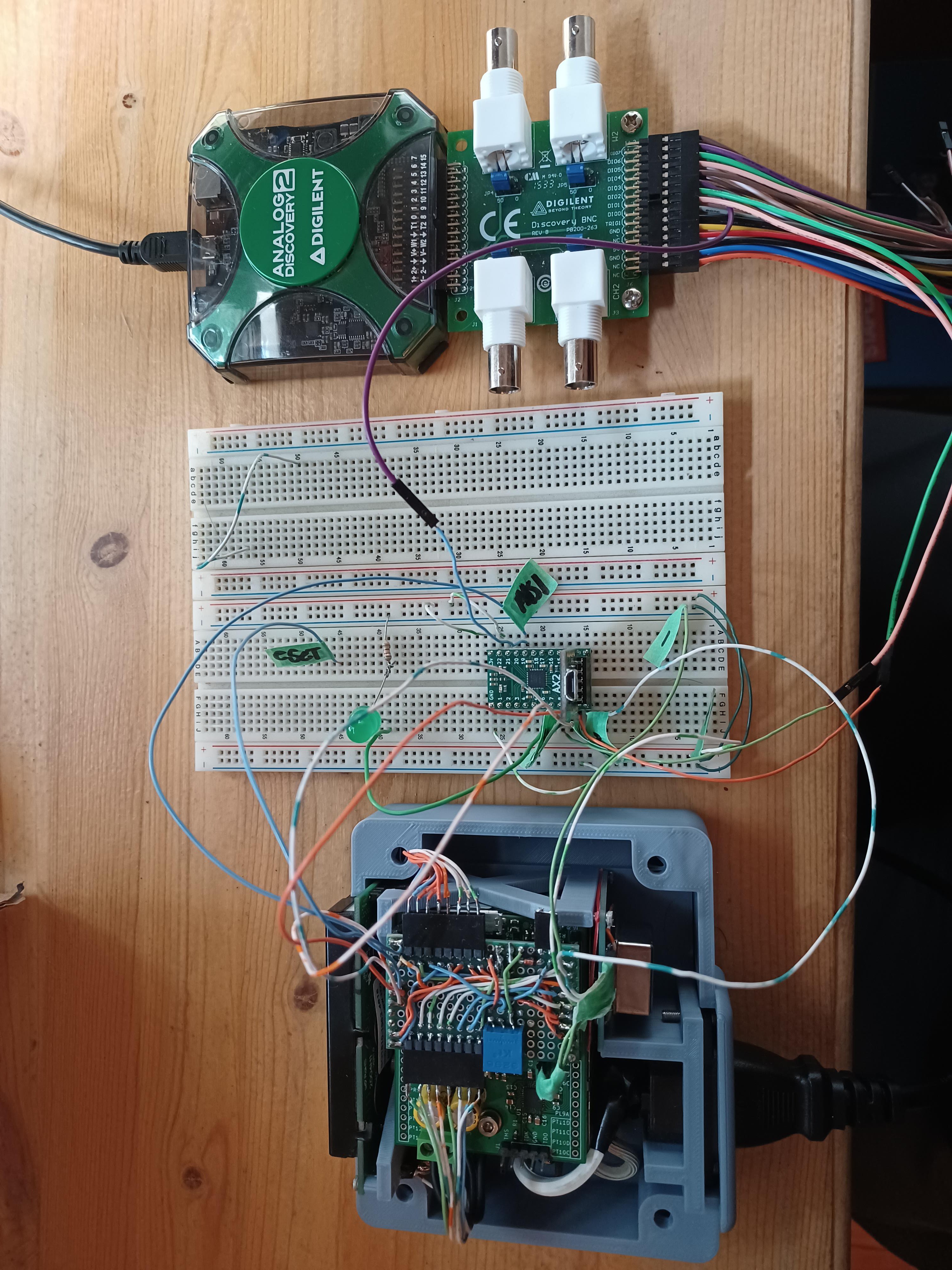
In the setup above the tinyFPGA devboard (on the breadboard) is counting pulses from the master oscillator (silver can near the AC plug in the image above), dividing the master frequency down to 1Hz, and then incrementing an epoch register every second. The ATmega (in the clock on the PCB) just periodically polls the FPGA for the current value in the epoch register over SPI, and then throws that value up on the display. So this test setup confirms the following:
- the FPGA is able to divide a signal down to 1Hz
- the FPGA is able to increment a register and communicate this value over SPI (SPI FSM works)
- the micro is able to update the display
- the micro is able to communicate over SPI with the FPGA
As the image below demonstrates, this was mostly a success:
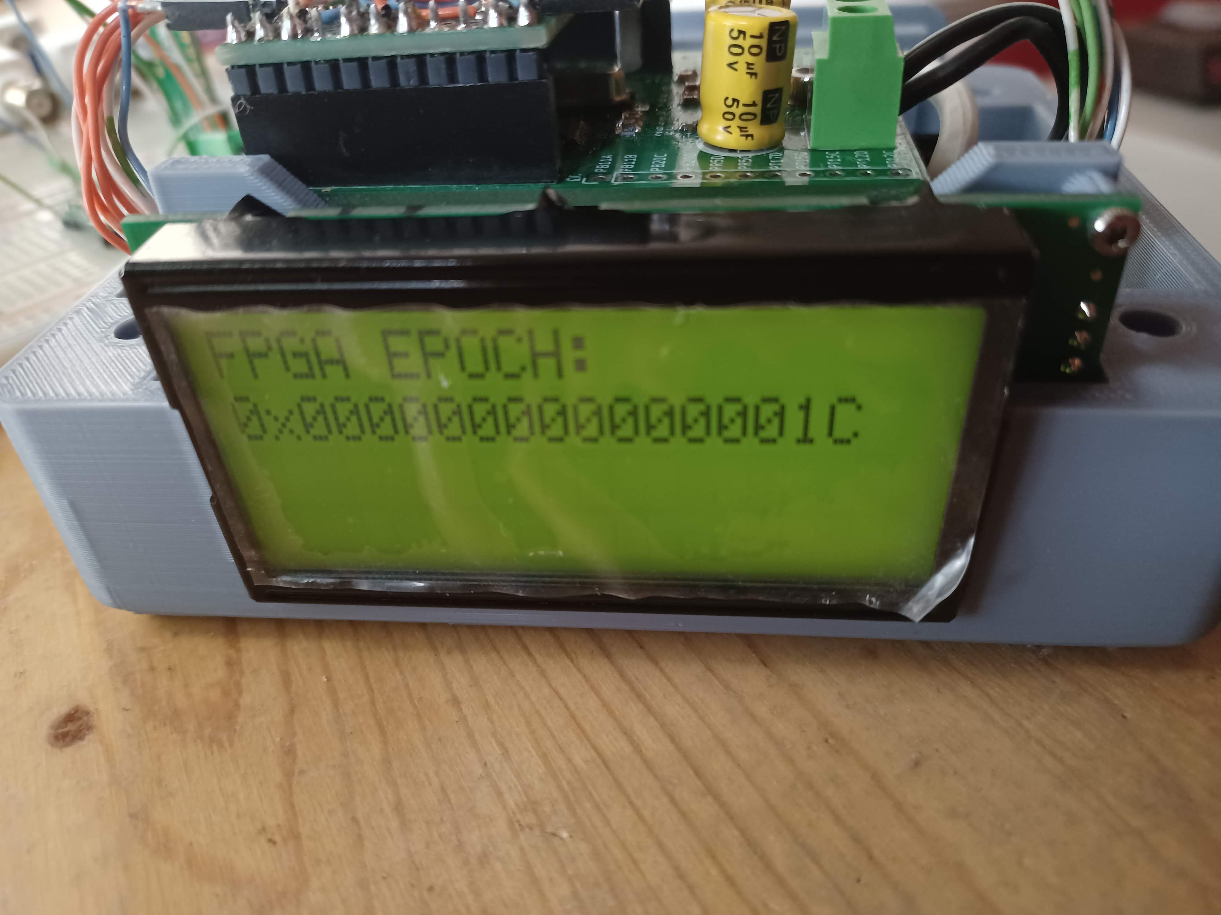
here the clock is showing that the FPGA has counted 64'h1C (?'d28) seconds since the clock was turned on. Since the master frequency is 20MHz this means that the FPGA has counted 28*20 = 560 million edges, and reported this over a spi connection.
In theory all of the code/logic to do this all ready existed in a working state from the last time I was working on this project, but it took a while to remember how it all went together. (mysteriously I also had interrupts misconfigured in the 'good' version of the code, which took way too long to debug). But this means that we have a known starting point to begin working on changing the FPGA to a part that is actually available, which is what the next couple of project logs will discuss.
As you probably guessed from the title of this post, dear reader, there is some qualification to the success described above. And that is that the clock is really really inaccurate right now, and the FPGA occasionally loses the state of the epoch register and rolls over to 0x0 prematurely.
There is an obvious problem with the above setup that certainly contributes to (and may be the source of) the above problem; that is that the 20MHz master frequency signal is being dumped right into a breadboard in order to connect to the tinyFPGA. This is suboptimal to say the least. Hopefully a shorter more direct connection between the OCXO and the FPGA will reduce parasitic capacitences and improve the accuracy a little. However there are still other possible sources of error:
- the OCXO's real frequency is not its nominal frequency and this will introduce a systematic error in the epoch count.
- I'm not worried about this though because it should be easy to calibrate out
- I also don't think that this is the primary source of the error that I'm observing
- more likely something is wrong with the logic in the FPGA
- it could be missing edges from the master oscillator (contributes to poor accuracy)
- it is likely also missing some edges on internal signals and therefore rolling over when it shouldn't, its not clear which logic block this is occuring in, (could be the divider or the epoch counter), but this would potentially explain the poor accuracy and the premature roll over that is observed
- this is a more pernicious problem, and will likely require some deeper FPGA magic to resolve...
despite these qualifications, I'm still happy with the state of the project. Right now my focus is on getting a different FPGA integrated into the system, and getting back to this state, but with an FPGA that I can actually source, which is what I'll blog about next. After that we can work on hunting down all of the sources of error in the clock.
Discussions
Become a Hackaday.io Member
Create an account to leave a comment. Already have an account? Log In.