 zaphod
in my last post I described the new revisions to the main PCB. They have arrived and I've successfully populated a v3.3 board.
here's a comparison shot of all 3 versions of the PCB:
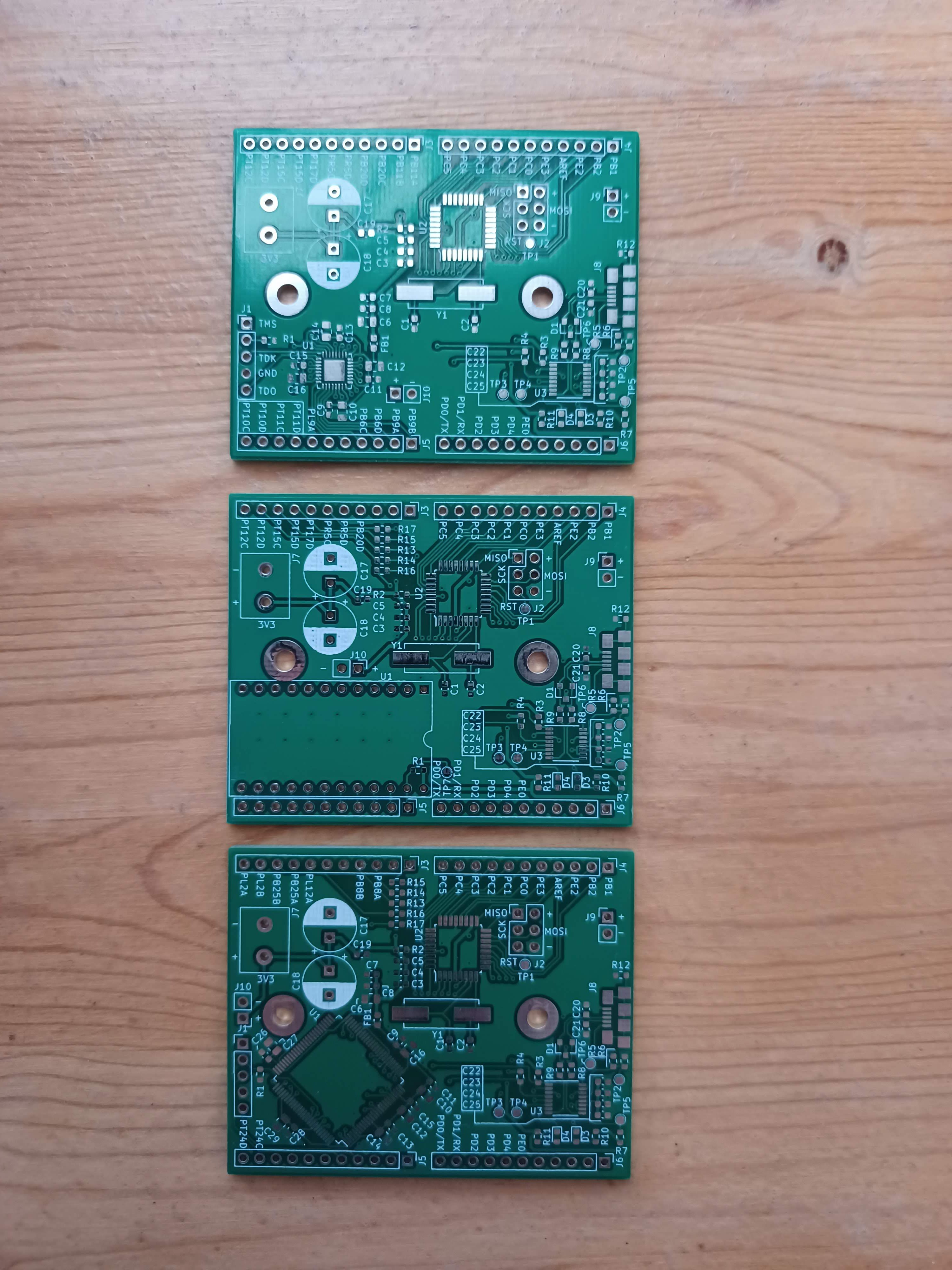
from top to bottom we have: v3.1, v3.2, and v3.3.
Basically everything is identical across all three version except the FPGA, v3.1 is designed to work with a 32QFN lmcxo2-1200hc part (the same as in the tinyFPGA Ax1), v3.2 is designed to include an entire tinyFPGA board, and v3.3 uses a 100TQFP lmcxo2-2000hc part.
As you'll recall I was unable to order more of the 1200hc parts and so I had to switch to the 2000hc part, which is unfortunately an order of magnitude more than I really need, but its at least in stock, and a package that I can solder. I basically designed the v3.2 as as back up in case the v3.3 didn't work, so I started bringup with the v3.3.
Assembly of the v3.3 board was pretty straightforward. Since the micro and FTDI circuits were exactly the same, they went together no problem. I did run out of capacitors though, and had to harvest some 0603 0.1uF from an old v1 board. Soldering on the 100TQFP was a pain, since I don't have a proper hot air station, but I got there in the end, all though I spent a lot of time hunting down and individually reflowing bad solders. I also had a nasty intermittently disconnected cold solder on one of the headers that attaches the main board to the display interconnect board, that took a long time to hunt down (I even ended up replacing the micro before figuring out that the intermittancy was due to a bad solder joint, and not a blown micro).
Since I all ready had test code ready to go I was able to confirm that the micro and FTDI chip were up an running pretty quickly. Getting the FPGA configured took some more effort though.
I'm using the tinyFPGA programmer for all of this, which is a little ten dollar USB->JTAG bridge with some software that's designed to make it go with the tinyFPGA Ax1 and Ax2 boards. However, the lmcxo2-2000hc-5tg100i is not one of the chips that is used on the Ax1 and Ax2 boards. I was hoping that it would just work out of the box anyway, but I was not so lucky.
I briefly considered getting the official Lattice JTAG programming cable, but its like $230, and even ebay clones are ~$30. Thus the only cost effective solution was to take a hack at the tinyFPGA programmer software: https://github.com/tinyfpga/TinyFPGA-Programmer-Application
From what I can see the tinyFPGA programming software consists of 3 major parts:
- the firmware on the PIC microcontroller located on the programming adapter. I didn't touch this, but I think its conceptually pretty simple: all it does is present a serial port to the host and manipulate some GPIO according to commands from the host. I don't think it even knows about the JTAG protocol, which I think is all handled by the host, but don't quote me on that.
- a python command line interface for talking to the serial port presented by the programming adapter. I think this cmd interface is technically human usable, but I always use the gui. This is the part that knows the JTAG protocol, and how to parse *.JED files.
- finally a little python gui that talks to the cmd interface and handle's some niceties like file picking and warning you when a programming file has been updated on the disk (link to this above)
The code base for the gui seems pretty stable, based on the github page, while the cmd interface seems to have had some more work done on it (the gui submodules an old version of the cmd interface).
To make a long story short, the reason that the gui wasn't programming my chip is that once it identifies an adapter it checks the IDCODE of the device that you're trying to program. IDCODEs uniquely identify the part number, and the programmer lets you configure the target if the IDCODE matches the chip used in the tinyFPGA Ax1 or Ax2. After some digging (page 187 of this: https://media.digikey.com/pdf/Data%20Sheets/Lattice%20PDFs/MachX02%20Family%20Handbook.pd ) I was able to figure out the IDOCODE of the lmcxo2-2000hc-5tg100i, and then add it to the list of known/acceptable devices. I was half expecting to need to do some more hacking, but once It could identify the attached device everything else just worked, and so my whole patch was like five lines:
diff --git a/tinyfpga-programmer-gui.py b/tinyfpga-programmer-gui.py
old mode 100644
new mode 100755
index f3a0f3e..254c539
--- a/tinyfpga-programmer-gui.py
+++ b/tinyfpga-programmer-gui.py
@@ -169,7 +169,6 @@ class TinyFPGAASeries(ProgrammerHardwareAdapter):

             def status_callback(status):
                 global port_success
-
                 if status == [0x43, 0x80, 0x2B, 0x01]:
                     com_port_status_sv.set("Connected to TinyFPGA A1. Ready to program.")
                     port_success = True
@@ -178,6 +177,12 @@ class TinyFPGAASeries(ProgrammerHardwareAdapter):
                     com_port_status_sv.set("Connected to TinyFPGA A2. Ready to program.")
                     port_success = True

+                # https://media.digikey.com/pdf/Data%20Sheets/Lattice%20PDFs/MachX02%20Family%20Handbook.pdf
+                # page 187
+               elif status == [0x43, 0xB0, 0x2B, 0x01]:
+                    com_port_status_sv.set("Connected to MachXO2-2000HC device. Ready to program, maybe...")
+                   port_success = True
+
                 else:
                     com_port_status_sv.set("Cannot identify FPGA.  Please ensure proper FPGA power and JTAG connection.")
                     port_success = False
the above goes in this file: https://github.com/tinyfpga/TinyFPGA-Programmer-Application/blob/master/tinyfpga-programmer-gui.py
(in retrospect I probably could have just short circuited the IDCODE check logic and saved my self digging up the datasheet with IDCODES in it, but this is marginally less ugly...)
also shout out to @Luke Valenty for making all of the tinyFPGA stuff open source (and cheap)!
Thus, with all of the chips on my board working it was time to dump in my test code/fpga logic. As you'll recall from the last time I got it ticking things were mostly working but the main counter in the FPGA was occasionally rolling back to 0x0 when it shouldn't have. This time there were no such glitches and its been ticking on my desk for 0x3A7C (14972) seconds, or about 249 minutes and 32 seconds:
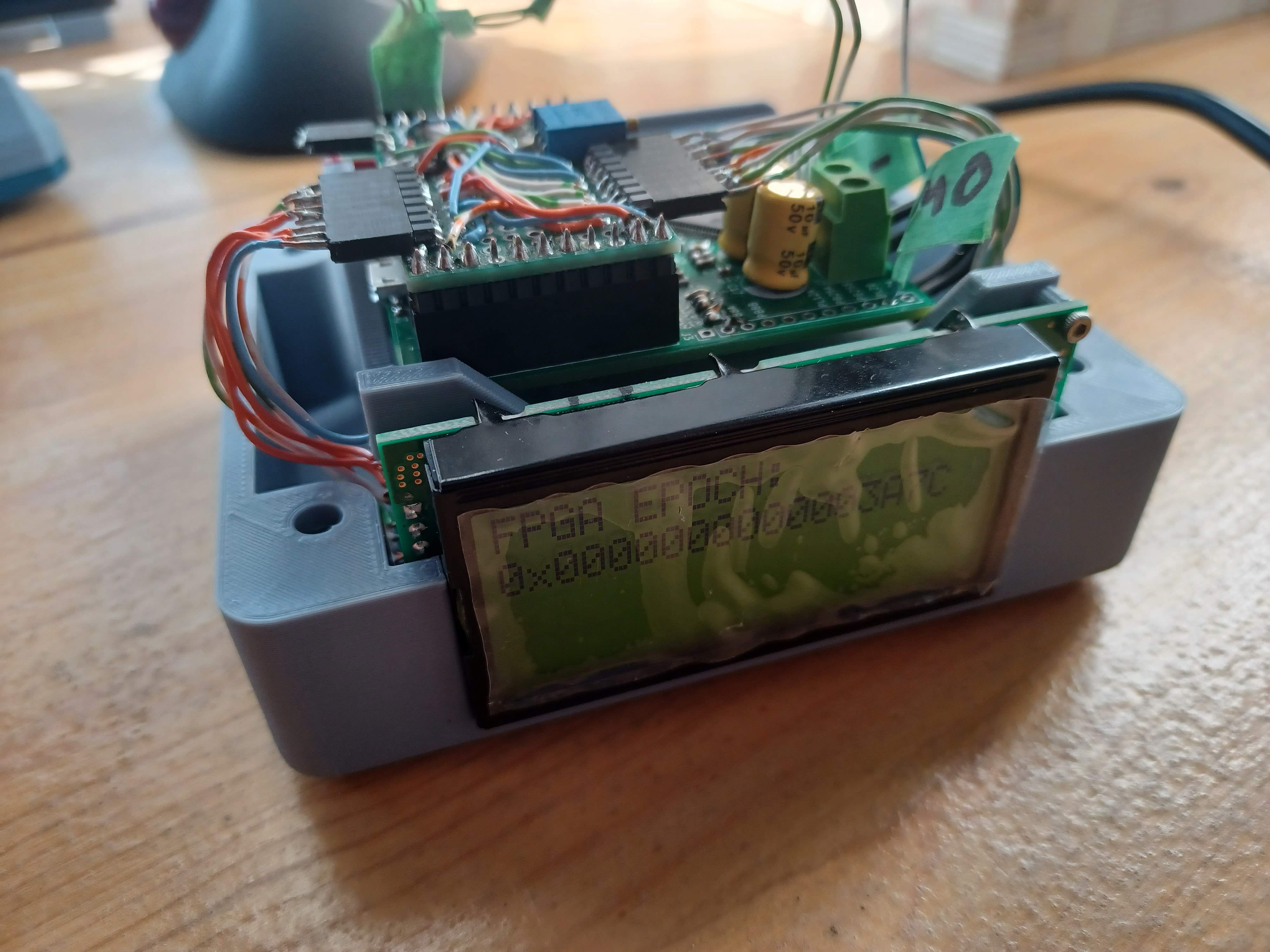
As a bonus that's even pretty accurate! I haven't done a careful accuracy measurement, so I wouldn't know its drifting unless it started missing minutes, but even so I'm pretty pleased, since this is the longest that I've run it from the OCXO, so I'm gald to see that it might be usablely accurate.
The final concern I have is that my FPGA logic just started miraculously working once I switched parts. I have a couple theories about this:
- the old lmcxo2-1200hc part I was using was pretty beatup and maybe about to die (I do think that I zapped one of the I/o at some point, so the rest of the chip might be sort of cooked too)
- the new part is a higher speed grade, and this means my sloppy logic works better since the new chip deals with the incoming master frequency better. This seems the most likely and implies that I ought to redesign the FPGA logic (or at least shuffle pins around to get the master freq on a high speed net)
- lucky routing on the FPGA, this also seems possible and I guess I'll find out when I try to change the verilog...
at any rate the next steps are:
- clean up all of the software/verilog and make sure everything is working
- do a careful check of the overall system accuracy, and hunt down all of the sources of error I can
- write all of the business logic to display a real time (not just a time stamp), as well as all of the set reset logic
- possibly write a client to set the clock to NTP over the serial port
but that's all "just software" (tm)
Discussions
Become a Hackaday.io Member
Create an account to leave a comment. Already have an account? Log In.