Close
0%
0%

Magnetic Field Visualizer

Using 3D Magnetic sensor to visualize a magnet's pole direction, heading, virtual field line & strength on an E-ink Display

Similar projects worth following
Using 3D Magnetic sensor to visualize a magnet's pole direction, heading, virtual field line & strength on an E-ink Display

About this project

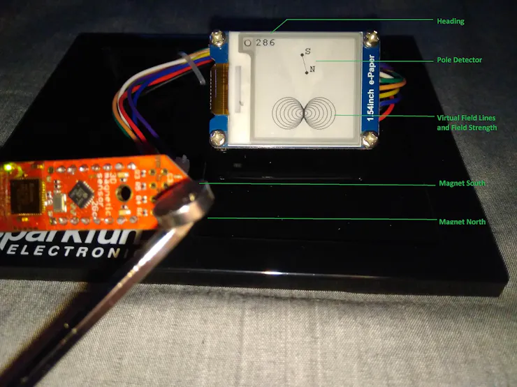
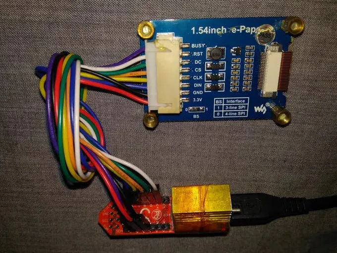
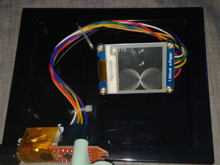
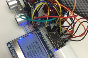
This project is about developing a simple magnetic field visualizer. Here, the XMC1100 is the system mcu with fetches magnetic field data of a nearby magnet from the TLV49 3D magnetic sensor. The mcu communicates with the sensor over I2C protocol. For visualizing the data, an E-Ink/Epaper display is added to the system. The display is 3.3 volts like rest of the system and communicates with the host mcu over SPI.

The display has 200 x 200 pixels and support for Black in White or White in Black imaging. As for the 3D magnetic sensor, it can sense up to +/- 130 mT in X, Y, Z direction of the sensor itself.

Display parameters

Display parameters

This visualizer can be used for :

  • Identifying North/South poles of a magnet
  • Magnet's orientation/heading on XY plane
  • Visualize virtual Field lines
  • Detect effective field area of a magnet
  • Compare magnets strength qualitatively

sch2.png

Wiring diagram

Portable Network Graphics (PNG) - 288.98 kB - 05/27/2021 at 00:35

Preview
Download

sch1.png

Schematic

Portable Network Graphics (PNG) - 561.81 kB - 05/27/2021 at 00:35

Preview
Download

FieldVisualCode.zip

Code ----- Unzip and compile with Arduino 1.8.5+ IDE

x-zip-compressed - 34.44 kB - 05/26/2021 at 23:41

Download

  • 1 × Infineon 3D Magnetic Sensor 2Go × 1
  • 1 × SparkFun Breadboard holder
  • 1 × Waveshare 1.54 E-ink Display
  • 1 × Small Magnet

  • 1
    Step 1

    Step 1: Hardware Connection

    Connecting the hardware is simple. The E-ink display is connected to the 2Go kit according to the schematic. The display operates on 3.3 volts, 4 wire SPI with few control lines.

    3 SPI I/O + 3 control I/O+ Vcc and Gnd

    3 SPI I/O + 3 control I/O+ Vcc and Gnd

    Now, the XMC2Go kit and the display is cable tied on a breadboard base.

    Step 2: Programming

    To program the system in Arduino IDE, the 2Go kit's board support must be added. This is done by following these steps -

    • Install and run Arduino IDE 1.8.5

    Adding 2Go kit support on Arduino IDE

    Adding 2Go kit support on Arduino IDE

    • Now go to Tools > Board Manager > type "xmc" in search box and download board support files

    Install board files

    Install board files

    • Now, we need Library for TLE493D 3D magnetic sensor.

    Go to: https://github.com/IRNAS/TLV493D-3D-Magnetic-Sensor-Arduino-Library

    Download the zip library and add to IDE

    Adding Library

    Adding Library

    • Next, Install Segger Link for communication between kit and IDE from here:

    https://www.segger.com/downloads/jlink/JLink_Windows_beta.exe

    • Then, go to tools and set

    Board : XMC1100XMC2Go

    Serial Output Selection : On Board

    Port : Port 11 (select whichever new port appears after plugging kit to usb )

    Setting up board, serial and program port

    Setting up board, serial and program port

    Step 3:Visualize Magnetic Field

    Check out this video to find what happens when magnet is moved towards and away from the TLV 493 3D magnetic sensor.

    Also, notice how rotating the magnet rotates the pole detector:

    Visualization
    • Pole detector is in phase with actual magnet's NS poles
    • Closer/Stronger the magnet, more field lines
    • Heading sweeps from 0 to 360 for each full rotation of the magnet

    What to expect?

    • Visualization is only applicable to single, symmetric magnet. Not applicable for complex magnetic field. For such application multiple sensors are required with high speed mcu and display.
    • The purpose of this visualizer is not quantitative measurements but qualitative ones, mostly for educational/entertainment purpose.
    • N-S poles of a magnet is shown with Pole Detector which is in phase with two dynamic dots connected with a line. Pole Detector rotates as the magnet rotates. It can be used to identify the north and south poles of a magnet, given that the magnet is suspended closely top of the 3D magnetic sensor.
    • 0 to 360 heading can be observed by rotating a magnet on the xy plane of the sensor.
    • Number of field line represents magnet's strength for a given position. It is suitable to compare 2 magnets placed at the same distance from sensor and find out which is more strong. Field lines do not rotate with the rotation of the magnet ( I tried but couldn't figure out the mathematical jazz )
    • The field lines are usually elliptic shaped, but due to API limitations, circular shaped field lines are used to represent field lines.
    • Better understanding of physics, mathematics and programming can improve the project.

    References

View all instructions

Enjoy this project?

Share

Discussions

Similar Projects

Does this project spark your interest?

Become a member to follow this project and never miss any updates