 Andreas Kahler
For Stereo Ninja testing we need an easy way to measure latency. A simple way is to put a smart phone with a stopwatch app in front of the camera and then take a photo with both the smart phone and the monitor displaying the smart phone on it. Then simply substract the time stamps shown and then you have the latency:
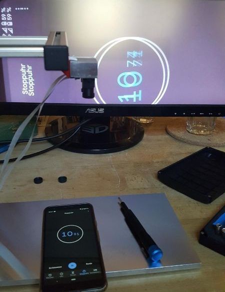
This kind of works, but the resolution is bad. The smartphone display has a refresh rate not fast enough to update the 10ms digit correctly. There is not even a 1ms digit. And then - because of the exposure time of the cameras - several digits are visible on top of each other, making it rather hard to read the numbers. (The photo shown above is a rather readable example. Note that the photo shows both the left and right eye image superimposed as no shutter glasses were used)
So we wanted something better...
Idea:
- On a 4 digit 7-segment display a counter, counting up each millisecond (or 10 ms)
- As before, this display is put in front of the cameras, and a photo is taken also showing the monitor
- Use a good photo camera to take the photo, ideally with a exposure time < 1/1000 sec
- To avoid blurring of the numbers, we do not display numbers for the least significant digit. Instead the segments of two 7-segment displays are used that form a kind of ring (using 5 segments of each display), which are lit up one after the other clockwise, like this:
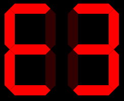
These are the 10 states:

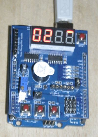
For the realization we used an Arduino Uno with a "multi functional shield" that can be cheaply bought on ebay or aliexpress.
The four 7-segment display are driven by two 74HC595. This allows using high multiplexing rates >1kHz which is a must for this project.
// Display milli seconds for latency measurements on 4-digit 7-segment display
// Written by Andreas and Simon Kahler

// Licensed under the Apache 2.0 license
// http://www.apache.org/licenses/LICENSE-2.0

/* Define shift register pins used for seven segment display */
#define LATCH_DIO 4
#define CLK_DIO 7
#define DATA_DIO 8

#define SW1 A1
#define SW2 A2

/* bits (0=LSB) for segments (1=off 0=on)
*
*        0
*       ---
*    5 |   | 1
*       ---
*    4 |   | 2
*       ---
*        3
*
*   center: 6
*   dot: 7
*
*/

/* Segment byte maps for numbers 0 to 9 */
const byte SEGMENT_MAP[] = {0xC0,0xF9,0xA4,0xB0,0x99,0x92,0x82,0xF8,0X80,0X90};

/* Segment byte maps for numbers 0 to 9 with dot */
const byte SEGMENT_MAP_WITHDOT[] = {0x40,0x79,0x24,0x30,0x19,0x12,0x02,0x78,0X00,0X10};

/* Segment byte maps for "clock ring 1 digit" */
const byte SEGMENT_MAP_RING[] = {0xFD,0xFB,0xF7,0xEF,0xDF,0xFE};
/* Segment byte maps for "clock ring 2 digit, right and left" */
const byte SEGMENT_MAP_RING2R[] = {0xFE,0xFD,0xBF,0xFB,0xF7,0xFF,0xFF,0xFF,0xFF,0xFF};
const byte SEGMENT_MAP_RING2L[] = {0xFF,0xFF,0xFF,0xFF,0xFF,0xF7,0xEF,0xBF,0xDF,0xFE};

const byte SEGMENT_EQ = 0xB7; // =
const byte SEGMENT_D = 0xA1; // d

/* Byte maps to select digit 1 to 4 */
const byte SEGMENT_SELECT[] = {0x01,0x02,0x04,0X08};

byte mode = 1;
byte multiplier = 10;

void setup ()
{
  /* Set DIO pins to outputs */
  pinMode(LATCH_DIO,OUTPUT);
  pinMode(CLK_DIO,OUTPUT);
  pinMode(DATA_DIO,OUTPUT);

  pinMode(SW1, INPUT_PULLUP);
  pinMode(SW2, INPUT_PULLUP);
}

/* Main program */
void loop()
{
  if (digitalRead(SW1)==LOW)
  {
    sw1Pressed();
  }
  if (digitalRead(SW2)==LOW)
  {
    sw2Pressed();
  }
  long i = millis() / multiplier;
  /* Update the display with the current counter value */
  switch (mode)
  {
    case 0: // 4 digits
      WriteNumberToSegment(0 , SEGMENT_MAP[(i/1000)%10]);
      WriteNumberToSegment(1 , SEGMENT_MAP[(i/100)%10]);
      WriteNumberToSegment(2 , SEGMENT_MAP[(i/10)%10]);
      WriteNumberToSegment(3 , SEGMENT_MAP[i%10]);
      break;
    case 1: // 1 ring + 2 digits
      WriteNumberToSegment(0 , SEGMENT_MAP[(i/100)%10]);
      WriteNumberToSegment(1 , SEGMENT_MAP[(i/10)%10]);
      WriteNumberToSegment(2 , SEGMENT_MAP_RING2L[i%10]);
      WriteNumberToSegment(3 , SEGMENT_MAP_RING2R[i%10]);
      break;
    case 2: // 2 rings
      WriteNumberToSegment(0 , SEGMENT_MAP_RING2L[(i/10)%10]);
      WriteNumberToSegment(1 , SEGMENT_MAP_RING2R[(i/10)%10]);
      WriteNumberToSegment(2 , SEGMENT_MAP_RING2L[i%10]);
      WriteNumberToSegment(3 , SEGMENT_MAP_RING2R[i%10]);
      break;
  }
}

void sw1Pressed()
{
  switch(multiplier)
  {
    case 1: multiplier = 3; break;
    case 3: multiplier = 10; break;
    case 10: multiplier = 30; break;
    default: multiplier = 1;
  }
  for (int i=0; i<1000; ++i)
  {
      WriteNumberToSegment(0 , SEGMENT_MAP[1]);
      WriteNumberToSegment(1 , SEGMENT_EQ);
      WriteNumberToSegment(2 , SEGMENT_MAP[(multiplier/10)%10]);
      WriteNumberToSegment(3 , SEGMENT_MAP[multiplier%10]);
  }
}

void sw2Pressed()
{
  switch(mode)
  {
    case 0: mode = 1; break;
    case 1: mode = 2; break;
    default: mode = 0;
  }
  for (int i=0; i<1200; ++i)
  {
      WriteNumberToSegment(0 , SEGMENT_D);
      WriteNumberToSegment(1 , SEGMENT_EQ);
      WriteNumberToSegment(3 , SEGMENT_MAP[mode]);
  }
}

/* Write a decimal number between 0 and 9 to one of the 4 digits of the display */
inline void WriteNumberToSegment(byte Segment, byte Value)
{
  digitalWrite(LATCH_DIO,LOW);
  shiftOut(DATA_DIO, CLK_DIO, MSBFIRST, Value);
  shiftOut(DATA_DIO, CLK_DIO, MSBFIRST, SEGMENT_SELECT[Segment] );
  digitalWrite(LATCH_DIO,HIGH);
}
Results
Here is a test with a iPhone8 in photo mode ("measurement" photo taken with a DLSR):
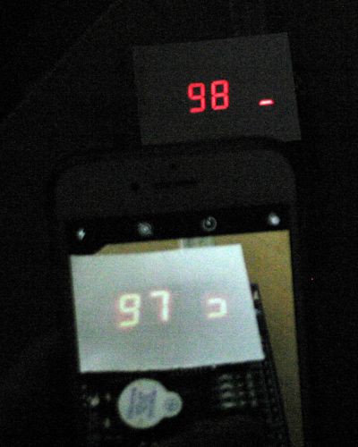
- A piece of paper was put on top of the 7-segment display, this made it easier to take a photo (display was overexposed otherwise)
- The Arduino code was run in 1/100sec mode
- 3 segments are visible on the iPhone display → exposure time is around 30ms
- The timestamp of the exposure is 9.73 to 9.75
- The timestamp of the measurement is 9.85
- Latency here is around 100ms (9.85 secs - 9.75 secs)
With a relatively long exposure time of 30ms on the iPhone and a latency of 100ms a measurement in 1/1000sec mode does not make sense here. But the concept seems to work nicely!
Next step: try it out with the Stereo Ninja!
Discussions
Become a Hackaday.io Member
Create an account to leave a comment. Already have an account? Log In.