 clewsy
Another write-up can be found at clews.pro.
The main features of this keypad include:
- HID compliant USB peripheral using an ATmega32U4 microcontroller with connectivity via a USB type-c connector configured as a USB 2 device. Power is also derived from the USB port.
- 21 mechanical keys (gateron blues which are pin-compatible clones of Cherry MX switches) with variable brightness white LED backlight on each key.
- In addition to the 17 standard keys of a numerical keypad, there is also a row of four keys across the top of the device which are programmable macros. (Well, all keys can be programmable macros, but this is how I have configured jank.)
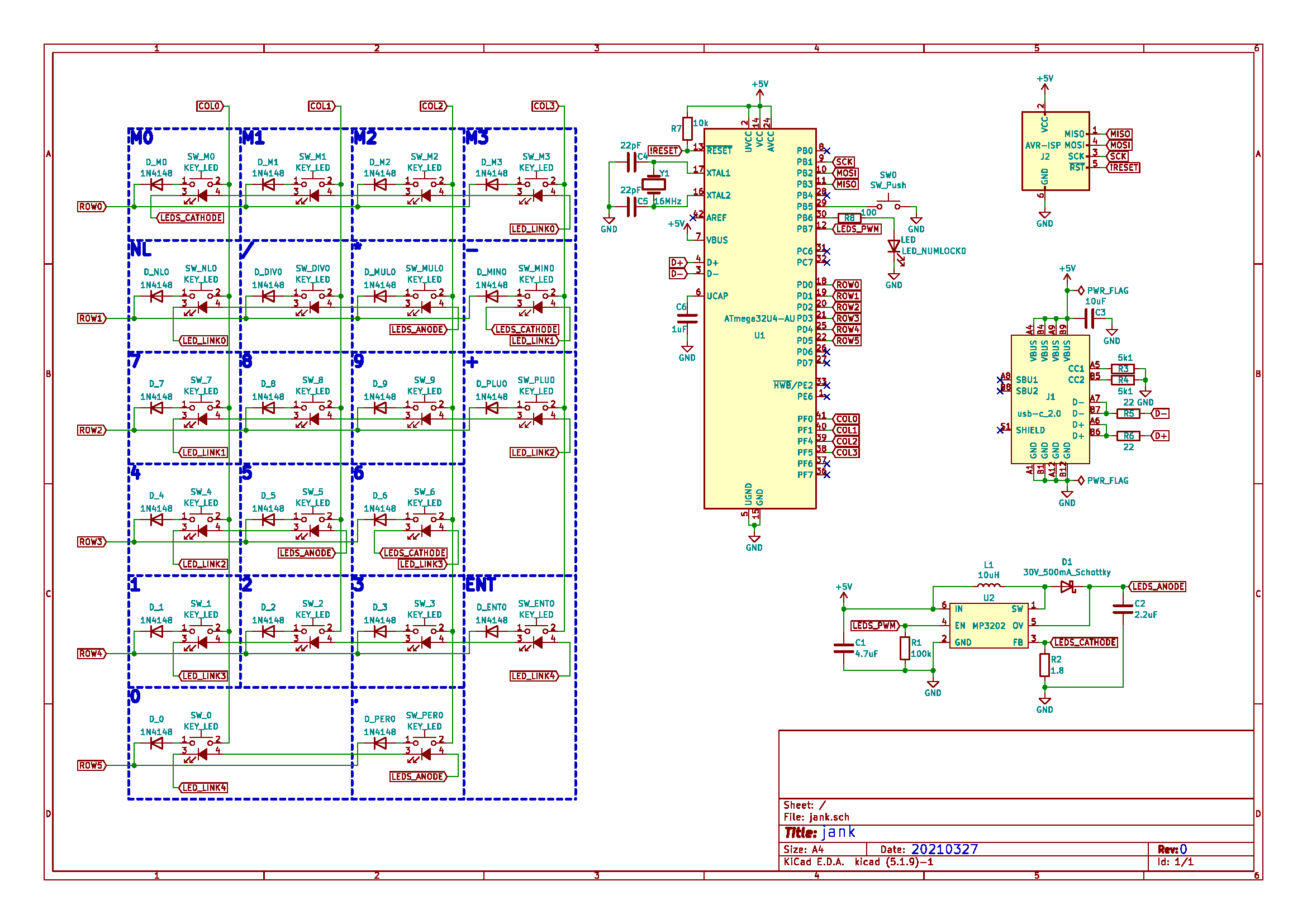
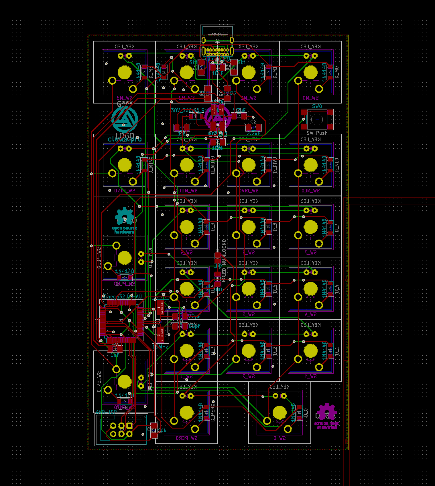
The schematic and PCB layout were designed in KiCAD. The schematic can be divided into five main areas/components:
- The key matrix - 21 gateron mechanical keyswitches connected in a matrix of 4 columns and 6 rows. The key switches each include a 3mm LED.
- ATmega32u4 AVR microcontroller - Selected because it has enough GPIO and hardware USB. I'm also familiar with the device from previous projects and have a few on-hand. Includes an external 16MHz crystal.
- MP3202 LED driver - I've not (successfully) used a boost LED driver before, so this was a neat learning experience. It drives all 21 keyswitch LEDs and is enabled by a PWM signal from the AVR which allows variable LED brightness.
- USB type-C Receptacle - Configured to be detected by a host as a USB 2.0 device. I went with a simple 16-pin through-hole connector that is (barely) hand-solderable.
- 6-Pin AVR ISP connector - A standard In-System Programming port.
The firmware can be separated into four parts:
- USB HID Implementation - Achieved by using Dean Camera's LUFA Library.
- Key Scanning - By sequentially enabling each row of the key matrix, then reading the state of each column, key scan functions determine which keys are pressed. The table below details the keyswitch layout and the corresponding row and column as connected to the microcontroller.
- Macro "typing" - The LUFA library made it easy to send regular keystrokes but I had to write some functions that would send a series of sequential keystrokes (i.e. to emulate typing).
- LED Control - Uses a timer configured as a PWM signal output on a pin connected to the LED controller enable pin. A tact-switch push-button on a pin-change interrupt is configured to cycle through various LED modes. The modes include various levels of brightness and a few pulsing effects. A second internal timer is used to vary the PWM duty cycle to provide the pulse effects.


 Albert Gonzalez
 Lauri Pirttiaho
 Voja Antonic
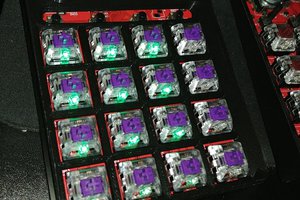
 Thomas
Nice!