Close
0%
0%

Exploring Flip Dots

I have this idea for a slow but relatively cheap flip dot display that I want to try out. This is definitely a research project.

Similar projects worth following
These are some of the questions I want to look into.

- What if the speed of dot flips is not a concern? So think updating a day of the week display rather than real time video.
- How do you drive the cost per "pixel" down?
- Is it really necessary for each dot to have an active element?
- How can the flip dot controller be simplified?
- How can power requirements be reduced?

Background

Flip dot displays are amazingly cool IMHO. There has been a lot of flip dot activity posted to Hackaday and elsewhere over the years. Larry Build's 3D PRINTED FLIP DOTS is just the latest example. While Larry's project involves creating flip dots from scratch, most of the work seen out there focuses on how to wire and drive commercial display units such as Pierre Muth's 30 FPS FLIP-DOT DISPLAY USES COOL CAPACITOR TRICK and like Larry's project the emphasis tends to be on the speed that dots can be flipped.

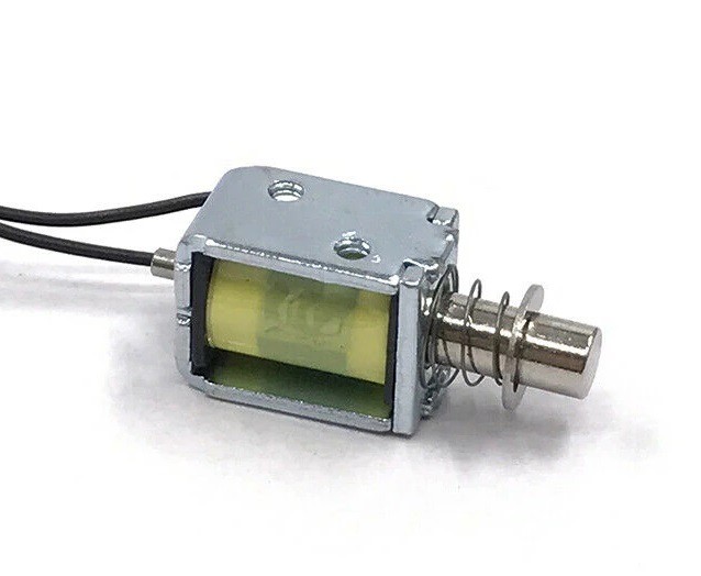
On the flip side, these dots is are relatively expensive.  New flip dot arrays can be on the order of $2 - $5 dollars per "pixel" or more. Often that number does not include the cost of control boards and power supplies. This is because each dot has an "active" element usually in the form of a solenoid that has to be powered and wired into a controller. 

Proof Of Concept

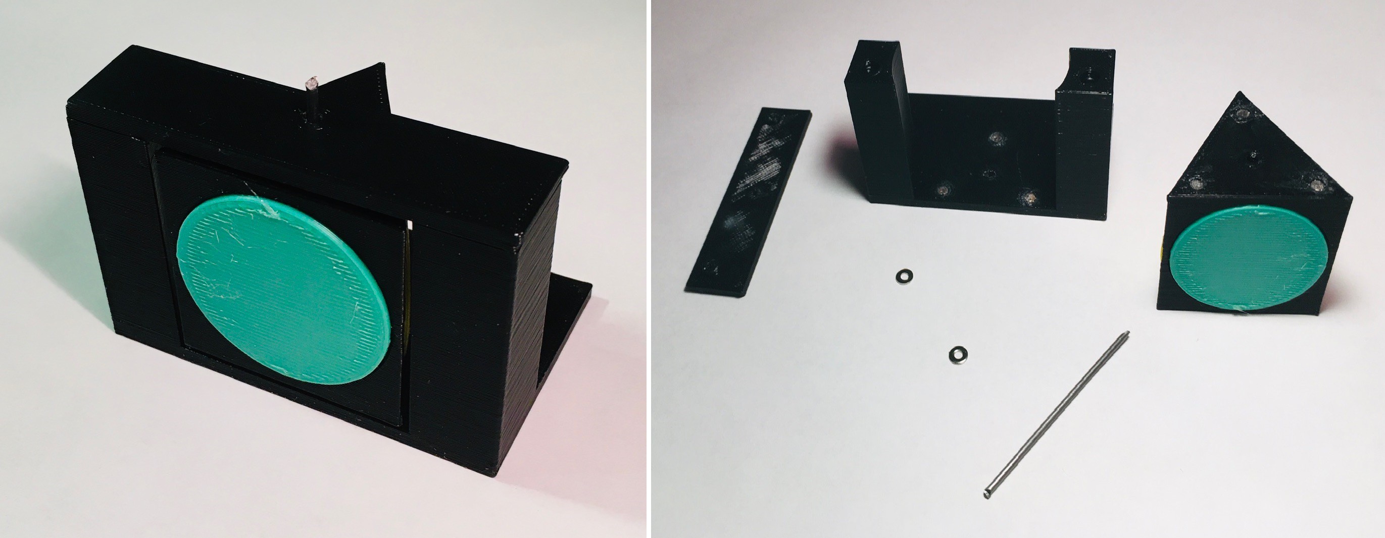
So far all I've actually made is a "passive" flip square. By passive I mean has no servo or solenoid. Here is what it looks like in action:

How It Works

So basically this element is just plastic, a little piano wire for an axel, and four small magnets. The square has small (3 mm x 1.7 mm) magnets imbedded in the center of the top and bottom edges. The supporting frame also has magnets with the opposite polarity embedded in the same central position top and bottom. 

When the slider is shifted to the front, it pushes the bottom of the square forward and the square's  magnets are "dislodged" from the frame's magnets. The momentum of the push is enough to spin it 180 degrees where the magnets again take effect pulling the square into the vertical position. The pusher tab also acts as a "stop" for the square as it swings around. So white becomes black.

The opposite happens when you pull the slider back.

Thoughts Moving Forward

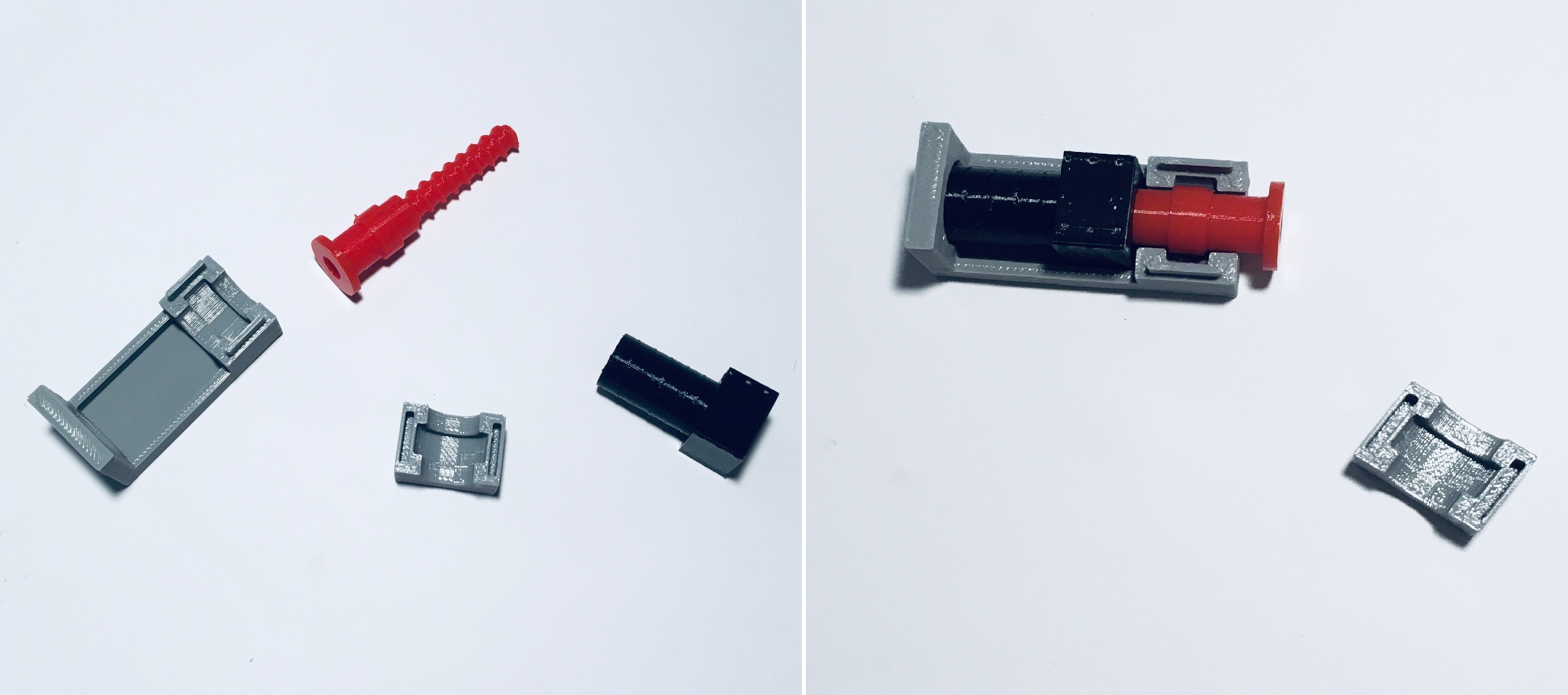
So it's not hard to imagine an X/Z array of these squares. Instead of having an active element on each, the idea is that a single active element (or a small number of active elements) will "visit" each square that needs to be changed and flip them. How this will happen mechanically is TBD. Think of a Core X/Z 3D printer where you replace the extruder with a solenoid or servo with a little "hand".  I'm short on details at this early stage but I think that such a mechanism would not have to be nearly as precise or as solidly constructed as a printer, so hopefully a lot less expensive.

No doubt with this scheme updating the display will be slow, but with the abundance of cheap steppers and drivers and readily available software available from the 3D printer world, hopefully the cost per "pixel" would be relatively low. 

  • Winding Down

    Michael Gardi08/30/2021 at 16:47 0 comments

    I haven't made much progress on this project probably because I don't have a pressing need right now for a large cheap slow flip dot display. Mostly I was just noodling with ideas.  So I'm going to close this project for now.

    If you are interested in pursuing this idea further you should check out : 

          https://hackaday.com/2021/06/24/mechanically-multiplexed-flip-dot/ 

    Not only did James Bruton come up with the perfect name (Mechanically Multiplexed Flip- Dots) for the concept that I have been trying to explore hare, he has produced a much more fully realized demonstration of how it would work with his 5 x 3 ping pong ball display.   

  • Trip-Dots

    Michael Gardi07/22/2021 at 21:35 0 comments

    I have to admit that I took some inspiration for this from Greg Zumwalt's wonderful 3D Printed Christmas Billboard. So in keeping with the idea of having a simple mechanical mechanism for each dot in a flip dot display I designed this tri-state display element.

    Like the bi-state flip square shown previously, this design uses magnets to "lock" the display into a stable position when a dot is facing forwards. (Note that the prism with the dots is shown on the right photo above upside down so that the magnets can be seen.) In addition when in the locked position, the backward facing vertex of the prism provides a perfect lever for an actuator to push the dot (in either direction) to the next state.  Here's how it works.

    It's even simpler mechanically than the push-push flip square.  There is still the issue of determining the current state of the visible dot. I think that this could be easily solved with some strategically embedded magnets and a couple of hall-effect sensors.

  • Mechanically Multiplexed Flip- Dots

    Michael Gardi07/22/2021 at 20:46 0 comments

    This was posted to the blog about a month ago: https://hackaday.com/2021/06/24/mechanically-multiplexed-flip-dot/. Not only did James Bruton come up with the perfect name for the concept I have been trying to explore hare, he has produced a much more fully realized demonstration of how it would work with his 5 x 3 ping pong ball display. 

    But the idea is the same. The 15 dots are controlled by only 3 servos and 1 continuous motor to move them across the display. Slow but relatively cheap. So cool.

  • Finding the Right Linear Actuator

    Michael Gardi06/17/2021 at 16:34 0 comments

    So with my new push-push flip square design I need a way to activate the change from one state to the other.  Some kind of linear actuator would seem to be ideal for this. In fact I will go so far as to say that a solenoid is probably the best solution. To that end I have ordered some small 3-5V push-pull solenoids.

    Since solenoid delivery is still many weeks away I decided to try something else. I really like what hugs is doing with his PinThing project. His linear actuator design is both elegant and compact. So I thought I would give his ideas a try. Now I created my version before hugs published his design so it's not quite the same or as good if I'm being honest, but for a test it gets the job done.

    I didn't have any suitable motors geared or otherwise to try this out with, but I did have some continuous rotation servos lying around. So here is the result. 

    A few things to note. The first is that this is such a cool idea. For hugs' PinThing project a perfect fit. For me not so much, at least with the slow servo rotational speeds. My actuator needs to impart enough of an impulse on the flip square sliders so that the square flips all the way around to the other side. At these speeds that is not going to happen. I have not completely given up on the idea though. I have some cheap "pager" motors with high rotational speeds on order.  

    It will be interesting to see if they can be controlled well enough so that the the linear actuator acts more like a solenoid.  I'll let you know what I find when they arrive many weeks from now.

  • Flipping Mark 2

    Michael Gardi06/03/2021 at 15:55 0 comments

    So say I make an XZ array of passive flip squares and I want to be able to spin them with a single "moveable" active element like a solenoid or servo. Mechanically how does this work? With my initial prototype I would have somehow had to reliably latch onto the slider bar in such a way that it could be pushed or pulled. Feels like this would be hard to do. So here is one way to simplify the problem.

    I changed the mechanism from push-pull to push-push. All I need to do now is move some sort of linear actuator into the correct position and activate it to set the element to either black or white.  I'm not sure it matters at this point but with this mechanism if an element is already black say and you try and set it to black nothing happens because the slider is already pushed in. But this leads to the question "Does the write head (linear actuator) need to be able to sense the position of the flipped square?".

View all 5 project logs

Enjoy this project?

Share

Discussions

Michael Gardi wrote 06/04/2021 at 14:50 point

Thanks for the encouragement John. Most of the time I have a pretty clear idea of what the end game is going to look like, but with this project I'm just exploring an idea. It's nice to know that at least one other person thinks it may have some merit ;-)  

The linear clock looks really cool and I'll certainly keep the threaded rod idea in mind as I proceed. 

I see you have also looked at PinThing. When I started I was thinking in terms of a single actuator, but PinThing's low cost  now has me considering multiple actuators (but nowhere close to one per pixel). I'm sure there is some sweet spot to be found in terms of performance, cost, and complexity.

  Are you sure? yes | no

John Opsahl wrote 06/03/2021 at 21:42 point

Great work. I think you may be on to something with a low-cost, low refresh rate, push-push flip dot. When the topic of a simple low-cost positioning system comes up, I always think of this linear clock concept (essentially a lead screw and nut) -> http://home.kpn.nl/bderogee1980/projects/linear_clock/linear_clock.html. It is essentially a 1.5 axis system that only requires one motor. Thinking it might be possible to control multiple flip dot rows just with one of these. Maybe multiple to control the entire display.

  Are you sure? yes | no

Similar Projects

Does this project spark your interest?

Become a member to follow this project and never miss any updates