 Radu Pascal
<TL>/<DR> If you just want to know the solution scroll down.
Problem (short)
I needed a (even dirty) source of reference frequency to calibrate a PFM3000.
Epic
So it all started when I was searching the internet on how to calibrate a Frequency Counter, after I acquired a second hand PFM3000. Not knowing if the previous owner played with the calibration pot or not, that was a must.
In my sailing through the rough seas of the world wide web, I found a paper describing the different methods and one of them was using a GPS module. Turns out GPS modules have the possibility of outputting a frequency that is as exact as any reference one.
Great! I have a couple of GPS module for my
RC airplanes. Can I use those? More sailing.
I decide to open the shield on one and discover it uses the M8030-KT (U-Blox). Searching through datasheets, yes, it has a configurable TIMEPULSE (whatever that is). But what pin is it connected to??? U-Blox don't provide pinout for their M8030-KT for the likes of us (hobbyists), and after more digging in the dark corners of the internet, I discover the chinese clone/equivalent chip AT6558R and it's datasheet which explains the pinout: https://datasheet.lcsc.com/szlcsc/1901021833_ZHONGKEWEI-AT6558R_C350653.pdf.
Playing with the multimeter I confirmed it that it is similar. But Still couldn't figure out which pin was the TIMEPULSE. Next I stumbled upon the Youtube video:
Doh.. I didn't have to waste so much time.. it's the Red Led pin!!
OK.. What next.. installing the U-Center from U-Blox and trying to configure the BN-220 through the nice UI.. (I wired the BN-220 through an Arduino UNO, and shorted the RESET pin to GND, yes you can do that!) I got the NMEA messages, but the configuration just wouldn't work.. no ACK came back. A few hours later I gave up on them.
Second day. I was still thinking that something is missing, since in the iNav it would auto-configure the GPS to another baud rate, refresh rate and use UBX. So why can't I use it in the UI??
I get my arduino Zero, find the library from Sparkfun https://github.com/sparkfun/SparkFun_u-blox_GNSS_Arduino_Library for M8 GPS chips and start hacking away.
2 hours later (after lots of stupid errors and bad documentation) I had the GPS module outputting the frequency of my liking. They even have a sample that does exactly that. Time for a nice cup of tea.
P. S. My PFM3000 was 1.4Hz off on 1MHz. Well within specs (2PPM).
Solution
You can use any U-Blox M8 module (or newer, I believe). Beitian BN220 was on hand so I just used that one. Need to check the protocol version that it's >=18 (the first lines when powering the GPS module).
Arduino Zero is the weapon of my choice because it's not using a serial chip so you have a dedicated serial for USB communication and another one for peripherals (also lots of horsepower that weren't used in this project).
Check the Instructions for wiring and sketch.
Results
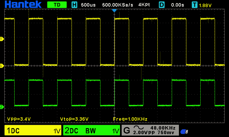
Yellow is the signal entering the resistor, green is the one exiting the resistor and entering the LED.
A pretty good square wave for 1KHz:
At 10KHz it's still good:

Things just start getting slightly messy at 100KHz, occasional spikes, and the waveform starts deforming:

At 1MHz we see a totally different picture:

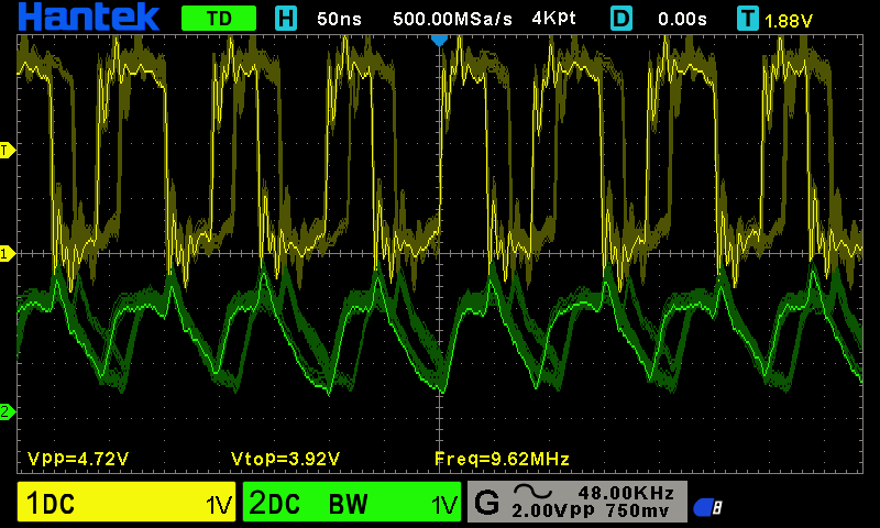
Next we have the 10MHz and that's where things go wrong, as the waveform is all over the place because of PLL trying to divide the 48MHz to get a 10MHz. There is no integer number to divide by. That's also where I stop trusting my Hantek and probes as to vertical accuracy.
My PFM3000 still managed to get an accurate reading, with just 14Hz error (within 2PPM).
12MHz - there might be some spikes that my Hantek can't catch, so I wouldn't trust it too much, but the main thing is the wave is very uniform, unlike the 10MHz:

And because I'm considering...
Read more »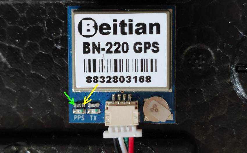
 Dilshan Jayakody
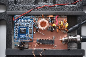
 Elia
Elia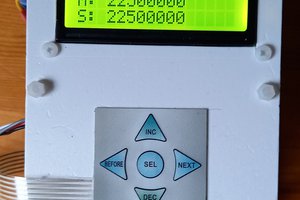

 Jesse R
There's an easier way to check or calibrate a frequency counter with a GPS module: leave the module at its default settings and measure the period of the PPS signal.