Dr.Stone
Intro
E-paper displays are fantastic for visual art but not fast enough for video or animation. Yet, I wanted to animate something in black and white canvas in slow motion. So, I made this badge!
Video Demonstration
Hardware: Initial Build
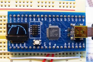
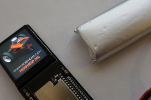
To build the hardware, two pieces of 2cmx8cm protoboards are glued side by side. Next, the XMC2Go board, LiPo battery, and 1.54-inch e-paper display are placed on the top of the protoboards.
_T512cvah9r.jpg?auto=compress%2Cformat&w=740&h=555&fit=max)
XMC2go (XMC1100 MCU board), paper display and battery
Inter-connections are made according to the schematic (below) and soldered with soldering iron.
_PX7sNyljRo.jpg?auto=compress%2Cformat&w=740&h=555&fit=max)
Soldering and interconnection on backside
Hardware Updated
Following updates are made later to the badge :-
- LiPo battery is placed under the display
- ADC sense (voltage divider) 5 user push switches installed
- Buzzer added for melody playback option with jumper to PWM pin
- I/O pins (ADC 1, PWM, I2C, Serial & Gnd) are routed for further development
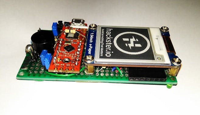
1 / 4 • PWM, ADC, I2C, Serial outputs (black female header under the display)
Programming
To program the system in Arduino IDE, the 2Go kit's board support must be added. This is done by following these steps:
- Install and run Arduino IDE 1.8.7
- Go to File > Preferences > Additional Board Manager URLs and paste https://github.com/Infineon/Assets/releases/download/current/package_infineon_index.json

Adding 2Go kit support on Arduino IDE
- Now go to Tools > Board Manager > type "xmc" in search box and download board support files
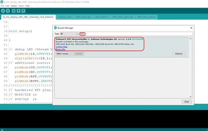
Install board files for version 1.1.0
- Next, Install Segger Link for communication between kit and IDE from here:
https://www.segger.com/downloads/jlink/JLink_Windows_beta.exe
- Then, go to tools and set
Board: XMC1100XMC2Go
Serial Output Selection: On-board
Port: Port 4 (select whichever new port appears after plugging kit to usb )

Artistic Images
Following images are printed one after another to create the illusion!
Scroll to right faster to see the effect of animation.
_aL7dbxxHzy.bmp?auto=compress%2Cformat&w=740&h=555&fit=max)
1 / 14 • 1
Image to Code Conversion
Monochromatic Bitmap images of 200 x 200 pixels are converted to code with Image2Lcd program according to following settings.

Image 2 LCD
These settings are critical, any deviation from these settings (marked in red polygon) might corrupt/mirror/rotate image output.

Placing image data in code imagedata.cpp
Each image/frame of 200 x 200 pixels is converted to hex data and copied to arduino IDE for flashing in the xmc1100 mcu.
Updating the header file imagedata.h is also required.

Updating imagedata.h header file
Technical Info
- The XMC2Go kit (XMC1100 mcu) has 16k RAM and 64k Flash for code.
- Each image frame (200 x 200 pixel) require about 4k Flash
- For the E-Paper display's memory buffer, 8k RAM is allocated
- Maximum 13 Frames can be stored inside program memory
- Power consumption during display update is 7.6 - 9.1 mA and during deep sleep 1.8 - 2.4 mA

RAM and FLASH Limit !
References
- XMC2Go in Arduino: https://github.com/Infineon/XMC-for-Arduino
- Segger J-Link: https://www.segger.com/downloads/jlink/
- Demo Code: https://waveshare.com/wiki/1.54inch_e-Paper_Module
- Image Source: https://daankusen.wordpress.com/2014/09/10/flying-is-easy/
- Gif to Bitmap: https://ezgif.com/split
- Bitmap to C : https://www.waveshare.com/wiki/File:Image2Lcd.7z
- Mario Melody: https://www.hackster.io/jrance/super-mario-theme-song-w-piezo-buzzer-and-arduino-1cc2e4
2Go Kit Modification for power source selection and LiPo Charging :- https://www.infineon.com/dgdl/Board_Users_Manual_XMC_2Go_Kit_with_XMC1100_R1.0.pdf
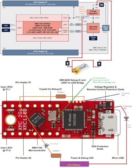
Power Selection between USB and LiPo
Badge Capabilities : Build Something That Matters
The badge says " Build Something That Matters " It's not just a badge. It will be used to make another project. The badge has following capabilities :
- Low Power Display Project
- Midi Playback
- I2C/ADC/Serial/PWM Breakout...
 pcadic
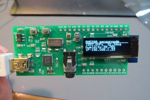
 kodera2t
 DKos_
DKos_