 hesam.moshiri
Infrared remote controllers are everywhere around us. The majority of home appliances are controlled using infrared remote controls. In this article/video, we learn to build a device that can decode (almost) any IR remote control and use the instructions to switch the relays (loads). So we can use this feature in a variety of applications without buying a new IR remote control and expensive hardware, such as turning ON/OFF the lights, opening/closing the curtains, ... etc. I have used an ATTiny85 microcontroller as the heart of the circuit. The device can record up to three IR codes in the EEPROM memory and switch 3 separate devices. Each relay can handle the currents up to 10A. The load switching mechanism (momentary ON/OFF, toggling, .. etc) can be programmed by the user.
I used Altium Designer 21.4.1 and the SamacSys component libraries (SamacSys Altium Plugin) to design the Schematic and PCB. I also used the Siglent SDS2102X Plus/SDS1104X-E to analyze the IR signals.
The device works stable and reacts well to the transmitted IR signals. So let’s get started and build this puppy!
A. Circuit Analysis
Figure 1 shows the schematic diagram of the device. As it is clear, both the decoding and switching tasks are done just by one 8-pins ATTiny85 microcontroller.
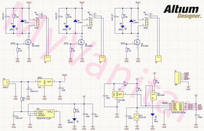
Figure 1, Schematic diagram of the infrared remote control decoder/switcher board
REG1 is the famous 7805 through-hole regulator [1] chip that prepares fixed +5V for the relays. C4 and C5 have been used to reduce the noise. FB1 and C11 block the input noise peaks. IC2 is the TS2937CW-5.0 regulator [2] that prepares a fixed +5V supply for the U1 and IC1. D8 indicates good supply provision and C8 and C9 have been used to reduce the regulator’s output noises.
U1 is the VS1838 infrared receiver module [3]. This module is sensitive to supply noises, so R7 and C6 build a low-pass RC filter to reduce the U1 supply noise even further. The output of the U1 has been connected to the PB3 pin of the IC1 and the gate pin of the Q4 Mosfet.
Q1 is the FDN360P P-Channel logic-level Mosfet [4] that has been used to supply the D7. D7 is an SMD LED that indicates the good reception of the infrared signals (blinks). R8 limits the D7 current. SW1 is an SMD tactile push button and C10 debounces the push-button mechanical contacts.
IC1 is the ATTiny85 microcontroller [5]. The ATTiny85 is a cute chip! that offers 8K flash memory and can run up to 20MHz with an external crystal oscillator. In this project, I set the clock to 8MHz-internal. C7 is a bypass capacitor and it has been used to reduce the supply noise.
Q1, Q2, and Q3 are the SI2303 N-Channel Mosfets [6] that are used to switch the K1, K2, and K3 relays. R4, R5, and R6 are pull-down resistors and D1, D2, and D3 are protective diodes. D4, D5, and D6 are relay activation indicator LEDs and C1, C2, and C3 are used to reduce the relays’ inductors’ noises.
ISP is a 5-pins male header that is used to program the IC1 using an AVR-ISP programmer. P1, P2, and P3 are 2-pins right angle phoenix connectors.
B. PCB Layout
Figure 2 shows the PCB layout of the infrared remote control switcher device. It’s a two layers PCB board and the majority of the components’ packages are SMD.

Figure 2, PCB layout of the infrared remote control switcher board
As I mentioned in the abstract, I used the Altium Designer software [7] to design the schematic and PCB. It is a neat piece of software that offers a user-friendly design environment and tons of useful features. I did not have the schematic symbol, PCB footprint, and the 3D model of several components in this project. So instead of wasting my time designing the libraries from scratch and increase the risk of errors and component mismatches, I used the free and IPC-rated SamacSys component libraries and imported them right into the Altium PCB project using the SamacSys Altium plugin [8]. SamacSys has provided plugins for the majority of electronic designing CAD software, not just for the Altium Designer. Figure 3 shows the supported electronic designing CAD software.
Figure 2, PCB layout of the infrared remote control switcher board
As I mentioned in the abstract, I used the Altium Designer software [7] to design the schematic and PCB. It is a neat piece of software that offers a user-friendly design environment and tons of useful features. I did not have the schematic symbol, PCB footprint, and the 3D model of several components in this project. So instead of wasting my time designing the libraries from scratch and increase the risk of errors and component mismatches, I used the free and IPC-rated ScamacSys component libraries and imported them right into the Altium PCB project using the SamacSys Altium plugin [8]. SamacSys has provided plugins for the majority of electronic designing CAD software, not just for the Altium Designer. Figure 3 shows the supported electronic designing CAD software.

Figure 3, Supported Electronic designing CAD software by the SamacSys plugins
Specifically, I used the SamacSys libraries for IC1 [9], IC2 [10], REG1[11], Q1…Q3[12], and Q4 [13], which you can consider the links in the references. Another option is to download the component libraries from componentsearchengine.com and import them manually. It’s up to you. Figure 4 shows the selected components in the SamacSys Altium plugin.
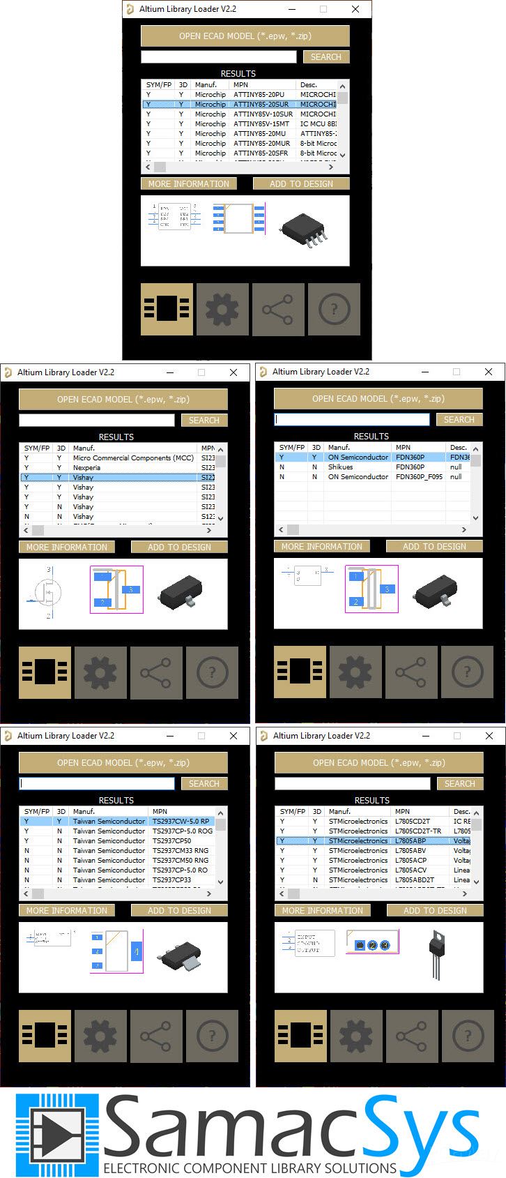
Figure 4, Selected component libraries in the SamacSys Altium plugin
C. Assembly and Testing
Figure 5 shows the assembled PCB board. The PCBs have been fabricated by the PCBWay company and I can say the quality is just fine. I had no problem with soldering the components. So I recommend you to look for quality and don’t select cheapies just for saving a few dollars!

Figure 5, Assembled PCB board of the infrared remote control switcher
C-1. Code
I have used the Arduino IDE to write the code, however, you don’t need to use an Arduino board for this purpose. You can install the custom ATTiny board manager and export the compiled binary (HEX file). Then program your chip using an AVR-ISP programmer or similar outside the Arduino IDE. You don’t need to program the bootloader as well.
#include <IRremote.h>
#include <EEPROM.h>


byte keyCounter = 0;
int data1 = -1, data2 = -1, data3 = -1;
byte out2Toggle = 0;


void setup() {
  pinMode(0, OUTPUT);
  pinMode(1, OUTPUT);
  pinMode(2, OUTPUT);
  pinMode(4, INPUT);
  IrReceiver.begin(3, DISABLE_LED_FEEDBACK);
}


void loop() {


  data1 = EEPROM.read(0);
  data2 = EEPROM.read(1);
  data3 = EEPROM.read(2);

  while (digitalRead(4) == 0)
  {
    if (IrReceiver.decode())
    {
      delay(200);
      if (keyCounter == 0)
      {
        data1 = IrReceiver.decodedIRData.decodedRawData;
        digitalWrite(2, HIGH);
        delay(2000);
        digitalWrite(2, LOW);
        EEPROM.write(0, data1);
        keyCounter ++;
      } else if (keyCounter == 1) {
        data2 = IrReceiver.decodedIRData.decodedRawData;
        digitalWrite(1, HIGH);
        delay(2000);
        digitalWrite(1, LOW);
        EEPROM.write(1, data2);
        keyCounter ++;
      } else if (keyCounter == 2) {
        data3 = IrReceiver.decodedIRData.decodedRawData;
        digitalWrite(0, HIGH);
        delay(2000);
        digitalWrite(0, LOW);
        EEPROM.write(2, data3);
        keyCounter = 0;
      }
      IrReceiver.resume();
    }
  }


  if (IrReceiver.decode())
  {
    delay(200);
    if (data1 == IrReceiver.decodedIRData.decodedRawData)
    {
      digitalWrite(2, HIGH);
      delay(250);
      digitalWrite(2, LOW);
      delay(250);
    }


    if (data2 == IrReceiver.decodedIRData.decodedRawData)
    {
      switch (out2Toggle)
      {
        case 0:
          digitalWrite(1, HIGH);
          out2Toggle = 1;
          break;
        case 1:
          digitalWrite(1, LOW);
          out2Toggle  = 0;
          break;
      }
    }


    if (data3 == IrReceiver.decodedIRData.decodedRawData)
    {
      digitalWrite(0, HIGH);
      delay(250);
      digitalWrite(0, LOW);
      delay(250);
    }
    IrReceiver.resume();
  }
}
To compile the Arduino sketch for the ATTiny85 microcontroller, you need to install the “ATTinyCore” by Spence Konde [14]. Similar board managers for Tiny chips don’t perform as expected. Also, install the “IRRemote” library V3.3 (By Armin Joachimsmeyer) [15] and include the header. For more details please check my YouTube video.
C.2. Testing
I have tested the output of the VS1838 module using the Siglent SDS2102X Plus oscilloscope [16] (figure 6). You can use other models as well, such as SDS1104X-E [17]. The oscilloscope screen says that the signal is clear and noise-free. Each remote control manufacturer might use an existing or its own infrared protocol and each remote key generates a different code, so the output signal of your remote could be different. I used a SONY HDTV remote control which naturally uses the SONY infrared protocol.

Figure 6, The output signal of the infrared receiver module (U1)
After successful programming of the microcontroller, please disconnect the programmer and restart the board (disconnect and re-connect the power). Then you can store the desired remote control keys (by pressing and holding the SW1). You can change any of the stored keys any time later. The keys are stored in the EEPROM memory, so the power reset does not clear the memory and the stored keys. For more details, please carefully watch the YouTube video.
D. Bill of Materials
Figure 7 shows the bill of materials.
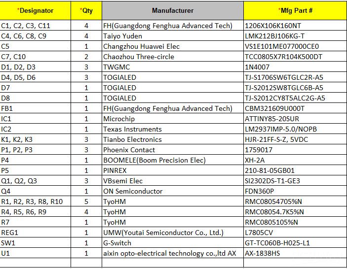
Figure 7, Bill of materials