My only two guidelines were:
- Minimize the number of servo motors.
- If possible, use only 3D printed parts.
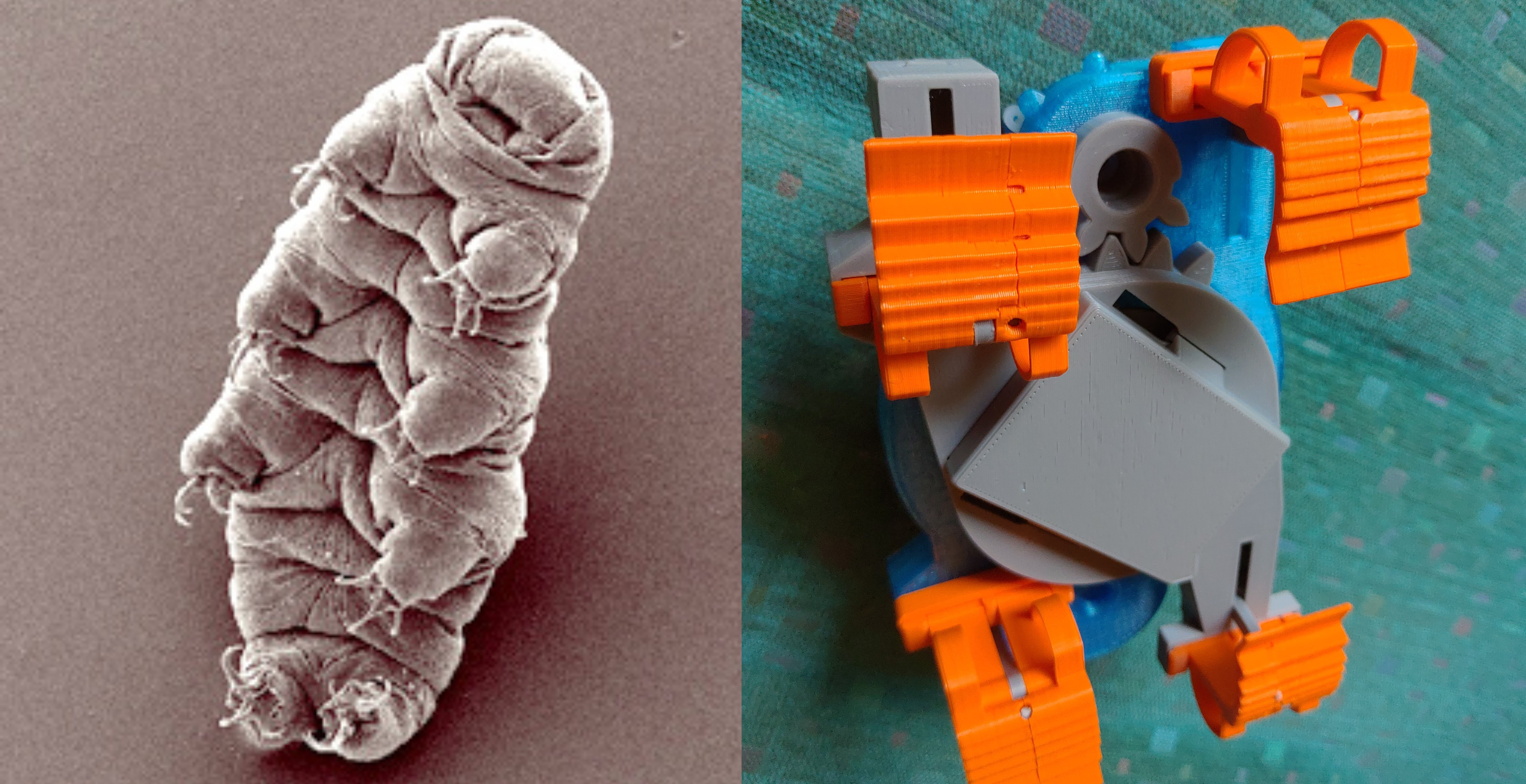
The design philosophy has been strictly utilitarian—function over form in every case. It was only after the fact I noticed that the thing ended up being rather cute, and looking a little bit like a tardigrade.
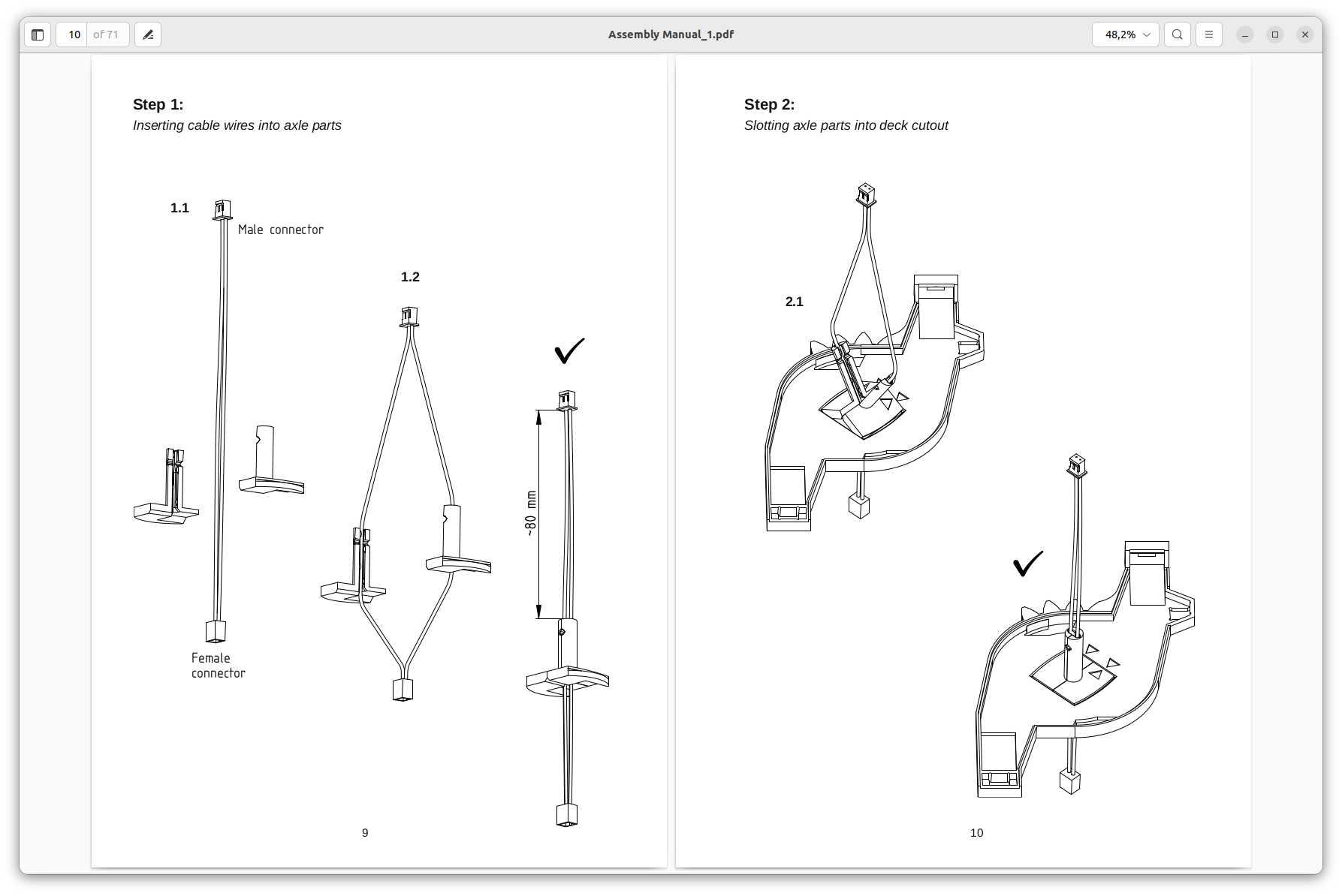
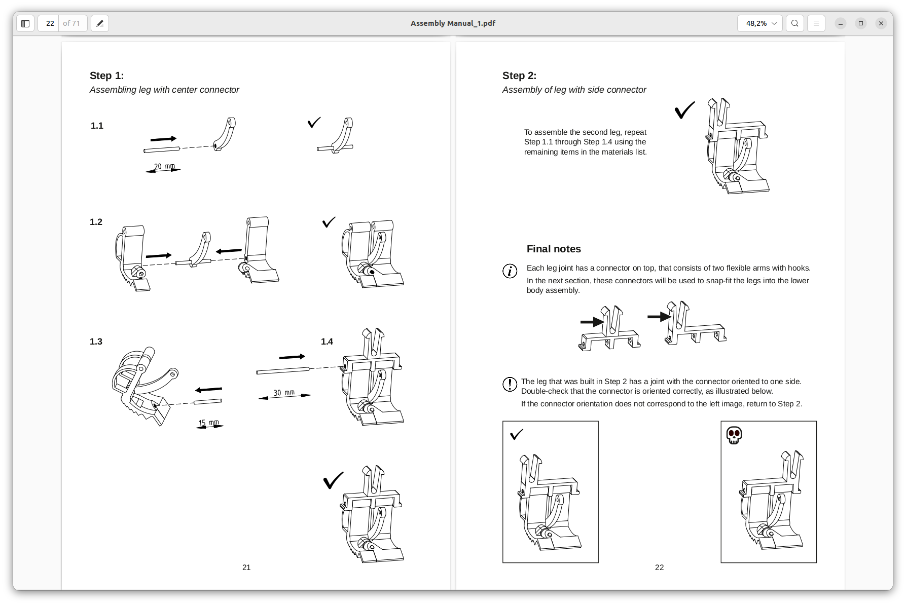
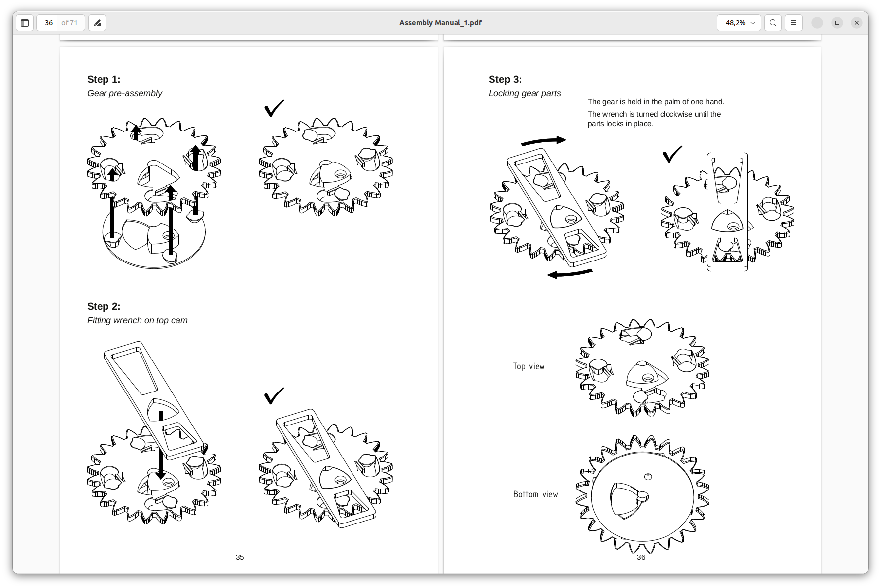
I've put a great deal of effort into making the robot body entirely 3D printable. Instead of screws or glue, Tardygrade relies on a combination ridges, snap fits and printer filament to keep itself together.
All in all there are 37 printed parts. Assembly should take about half an hour.
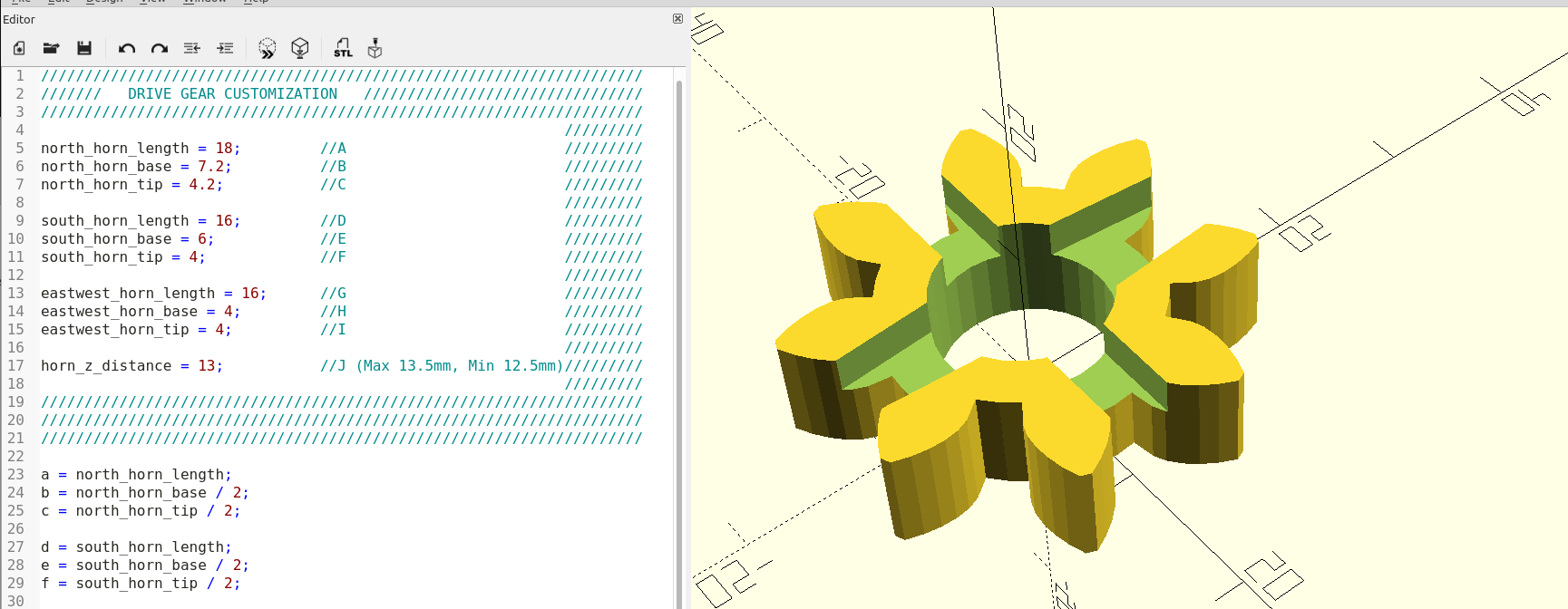
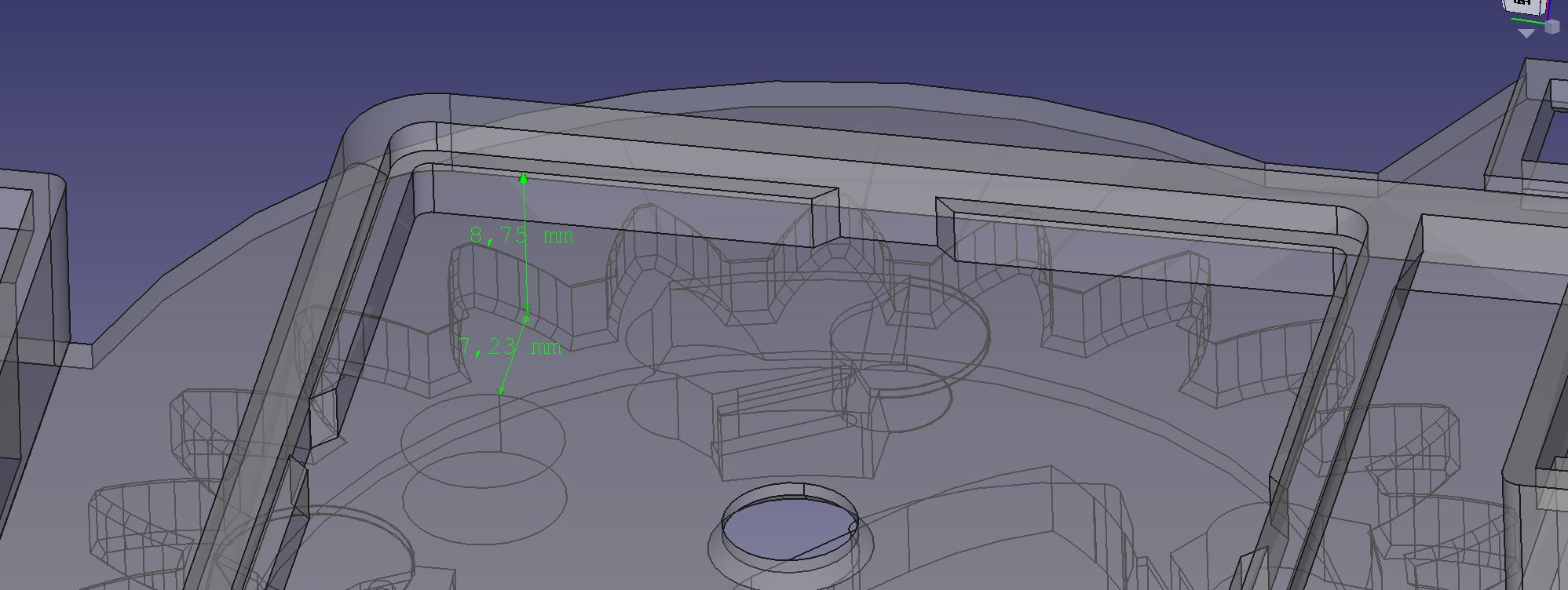
The 3D model is being developed using Free-CAD and OpenSCAD.
Controller
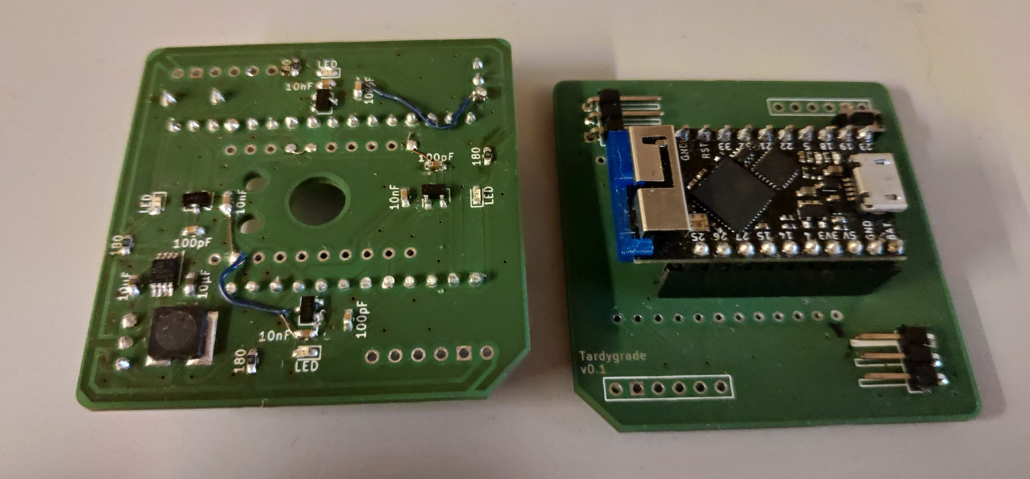
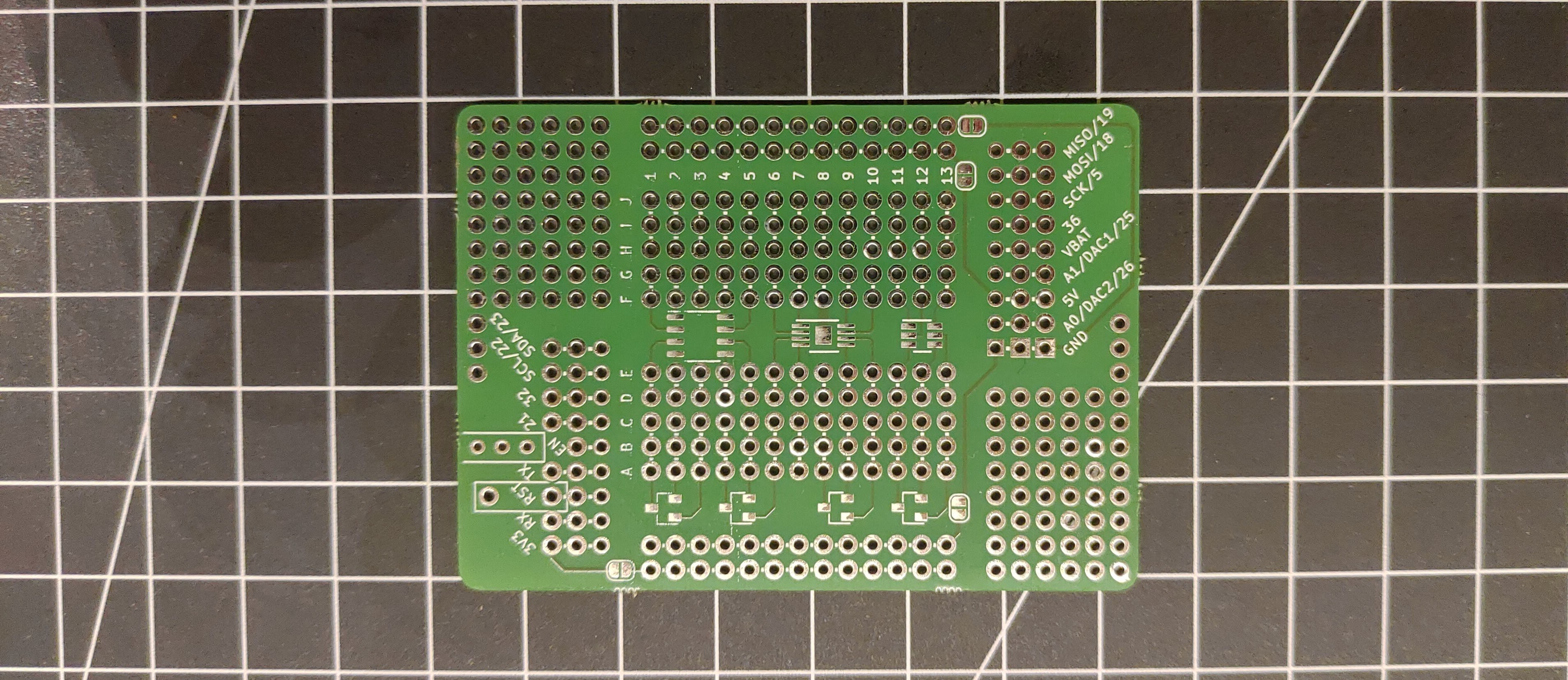
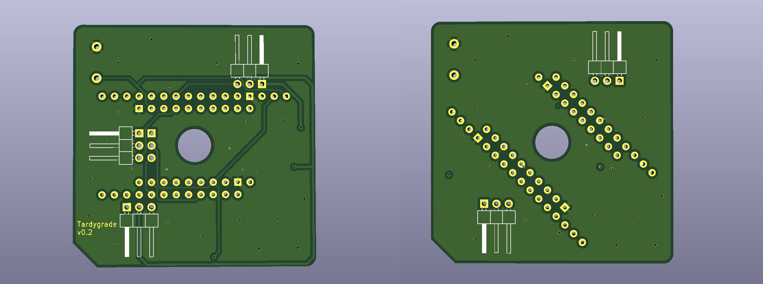
Automation control is based around the ESP32 µC. I'm designing a 5x5 cm printed PCB that acts as a shield for an ESP32 dev-board. The PCB has two pairs of pin headers, for compatibility with both the "Adafruit HUZZAH32 Feather" and the "Tinypico" form factors.
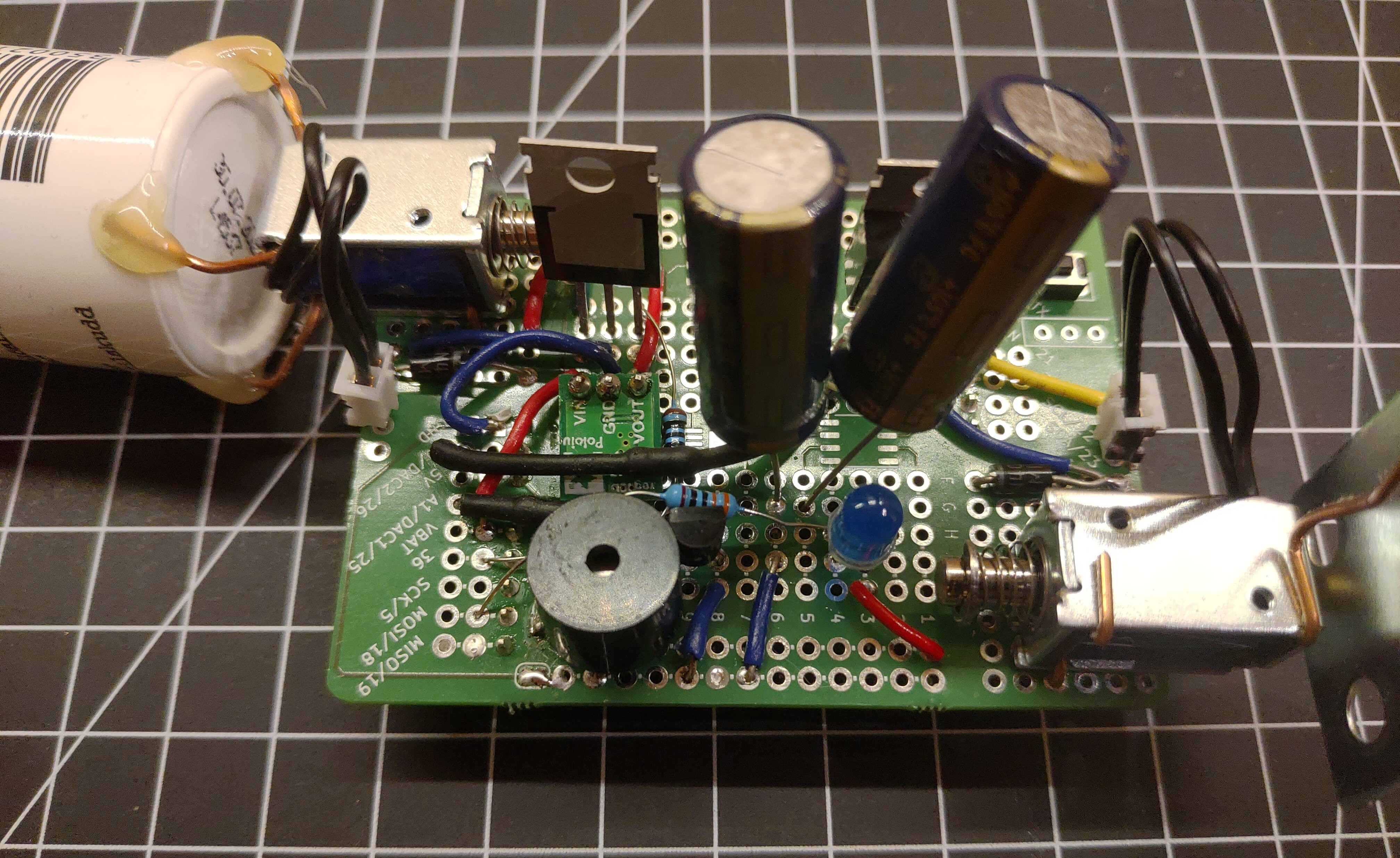
The shield has three main functions:
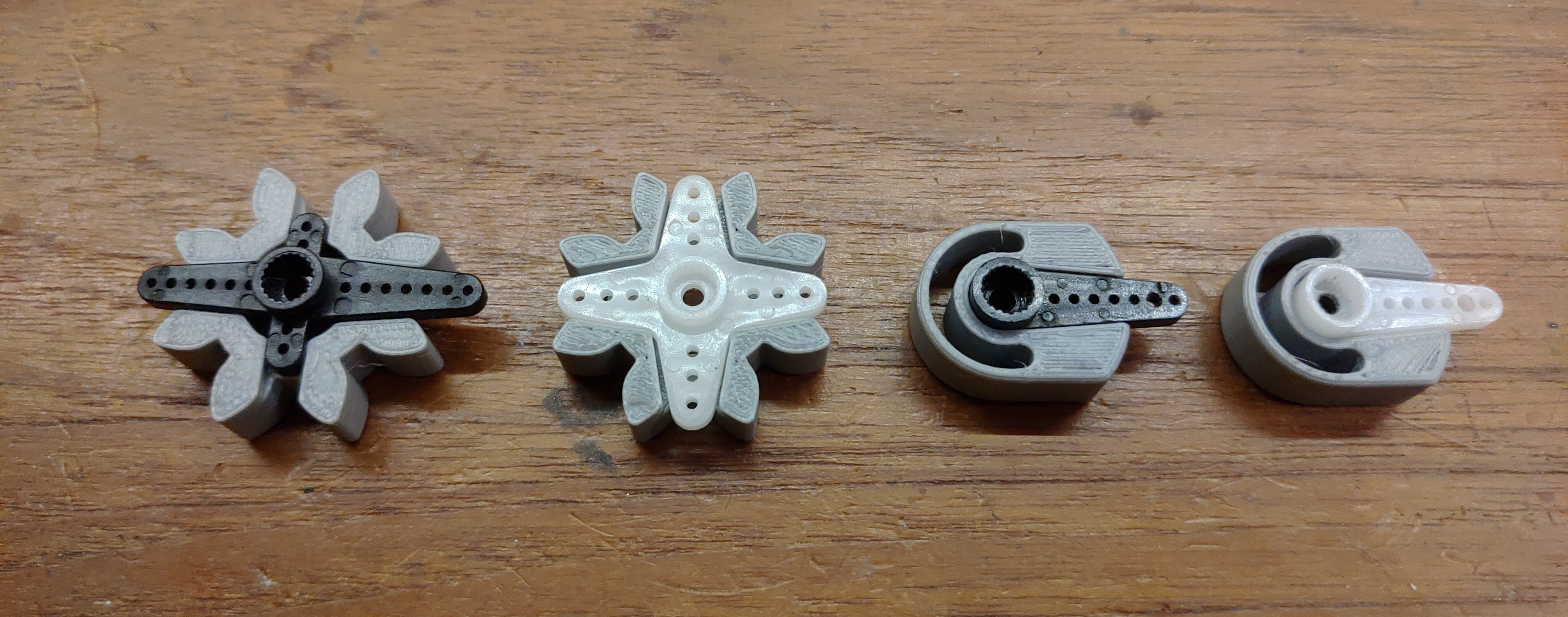
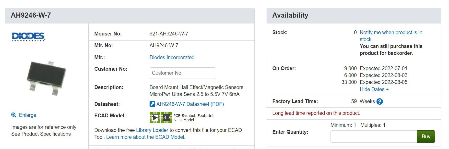
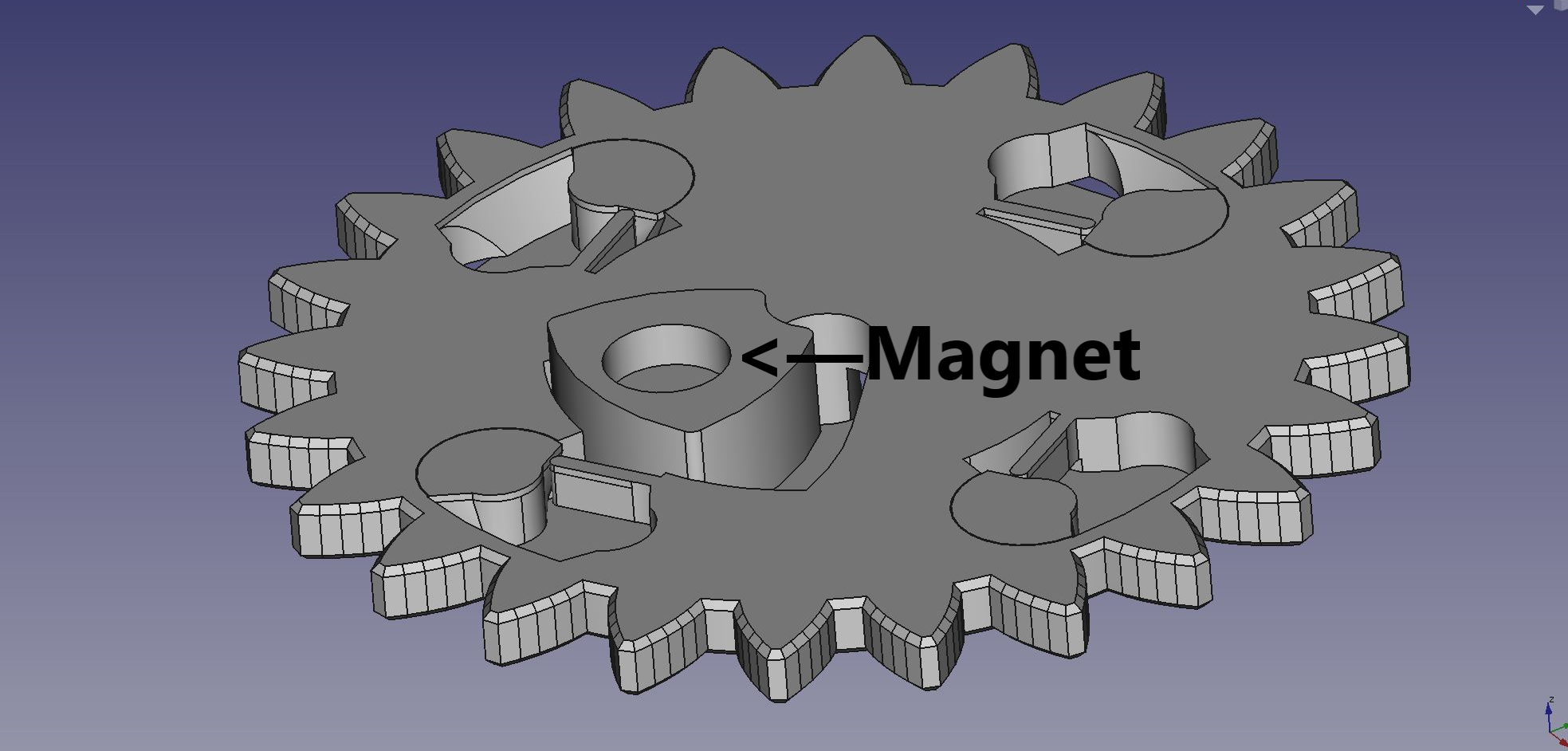
- Allows the ESP32 to perform motion control via four hall sensors, which detects the position of a magnet mounted inside the main gear.
- Voltage regulation for the servo motors.
- Hardware interface to laser distance sensors.
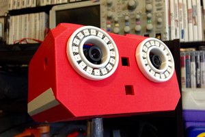
I'm also planning to add a downward-facing rgb led, to illuminate the robot body from within. There's no practical utility in doing that. I just think it would look cool.
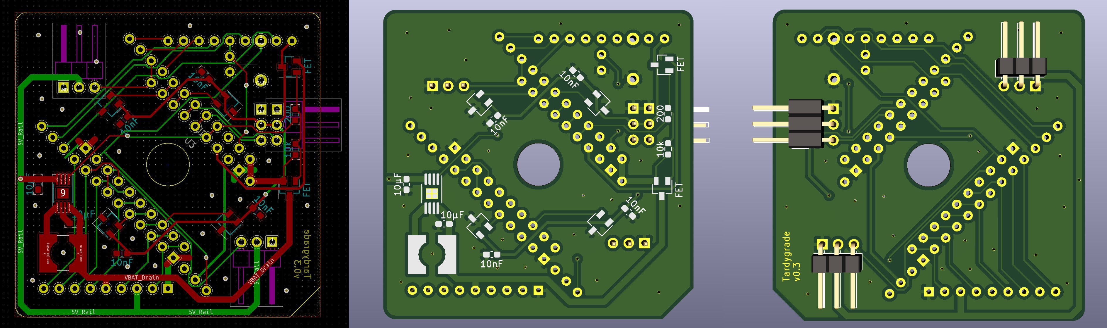
I'm designing the PCB using KiCad EDA. Prototype boards were made by Aisler.
Software
The automation software is being written in MicroPython.
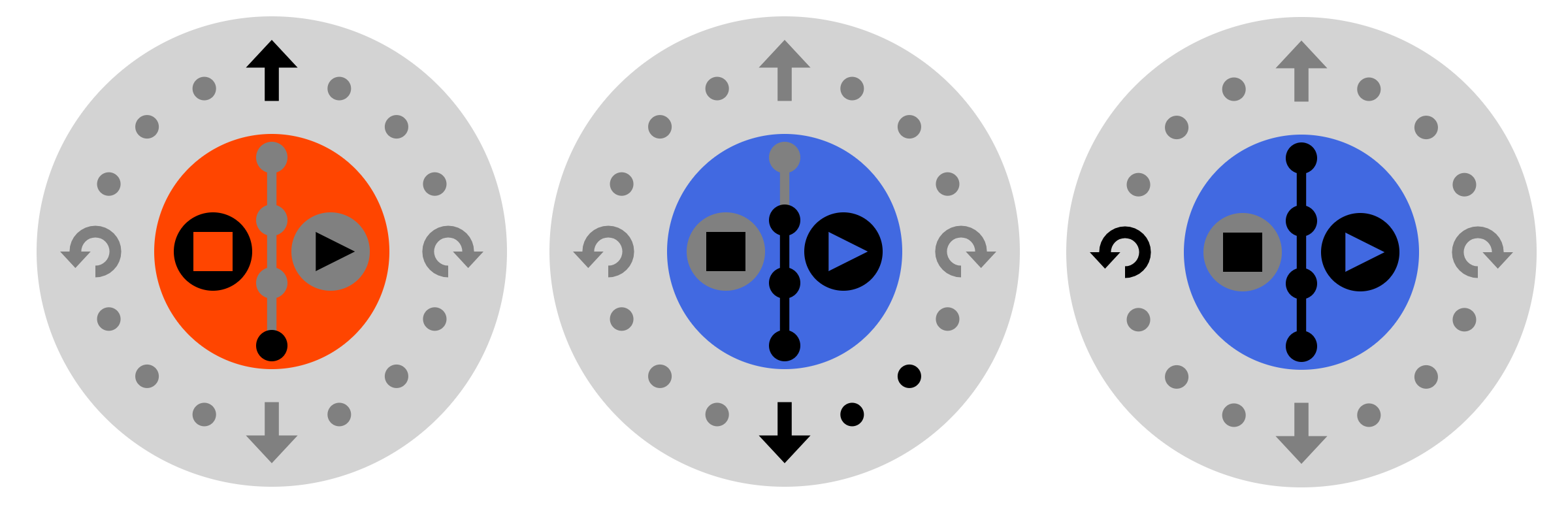
For web server on the ESP32 I use Microdot. User interface is written mainly in JavaScript, for remote control via a phone web browser. In addition, the web server provides HTTP endpoints for accessing all automation functions.
I will probably add some simple AI boilerplate that lets a Tardygrade fitted with distance sensors walk about autonomously. The boilerplate code can then be extended by users who want to experiment with their own AI code.
At some point I might start working on an Arduino port as well.
Source files
All project source files are available on GitHub under the creative commons licence.
| Bill of materials (pdf) | https://github.com/dejanristic78/Tardygrade-BOM |
| 3D CAD model (FreeCad) | https://github.com/dejanristic78/Tardygrade-3d-model |
| 3D printing files (stl) | https://github.com/dejanristic78/Tardygrade_stl_files |
| Controller PCB (KiCad) | https://github.com/dejanristic78/Tardygrade-pcb |
| Prototyping shield PCB (KiCad) | https://github.com/dejanristic78/Tardygrade-shield-pcb.git |
| Source code (Micropython, Javascript) | https://github.com/dejanristic78/Tardygrade-code.git |
| Build instructions |
Tardygrade is still under development, which means all features are not full-fledged yet. If you would like to build the robot right now, I recommend that you join the Tardygrade Discord server. I will offer support, and welcome all feedback.
PM me for details.

 Irene Sanz
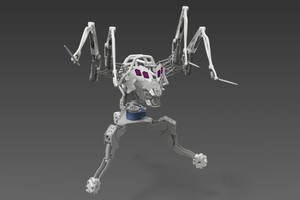
 Val
Val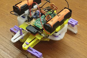
 ThunderSqueak
Congratulations on being a winner in the robots challenge--great project!