I was on a quest to rid the robot assembly of screws.
Eventually it was down to just the one. That was the screw that mounts the main gear axle to the robot upper body and essentially holds all parts of the body together.
It was a straightforward construction, but it came with a tradeoff. Since the axle is quite thin—and is parallel with the Z axis when 3D printed—it inevitably turns out somewhat brittle.

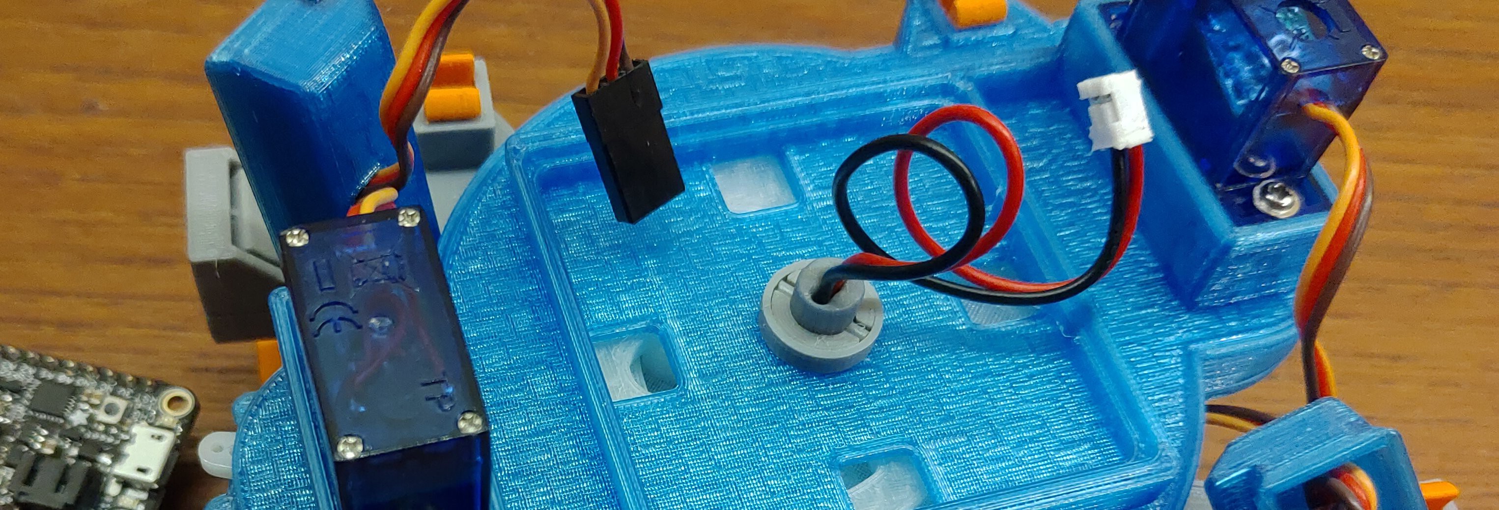
Meanwhile, I had also wrestled with how to gracefully route the leads from the battery located on the bottom of the robot up to the electronics on top. The current solution was to have the leads run up and around the left side of the body. That's ugly and also impractical since the wires would be prone to get tangled up on stuff.
So I started to noodle on if it actually would be possible to route the leads inside the main axle, since that happens to be the only path trough the body with no moving parts. The eye of the storm so to speak.
But that's where the screw needs to go! Now how do I attach the axle to the upper body?
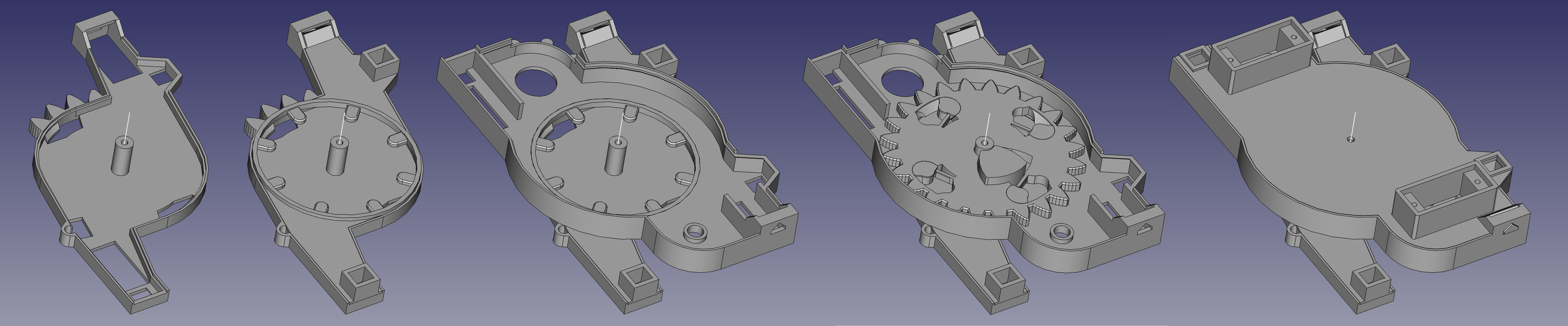
It took a while figuring out, but finally I ended up with this solution:
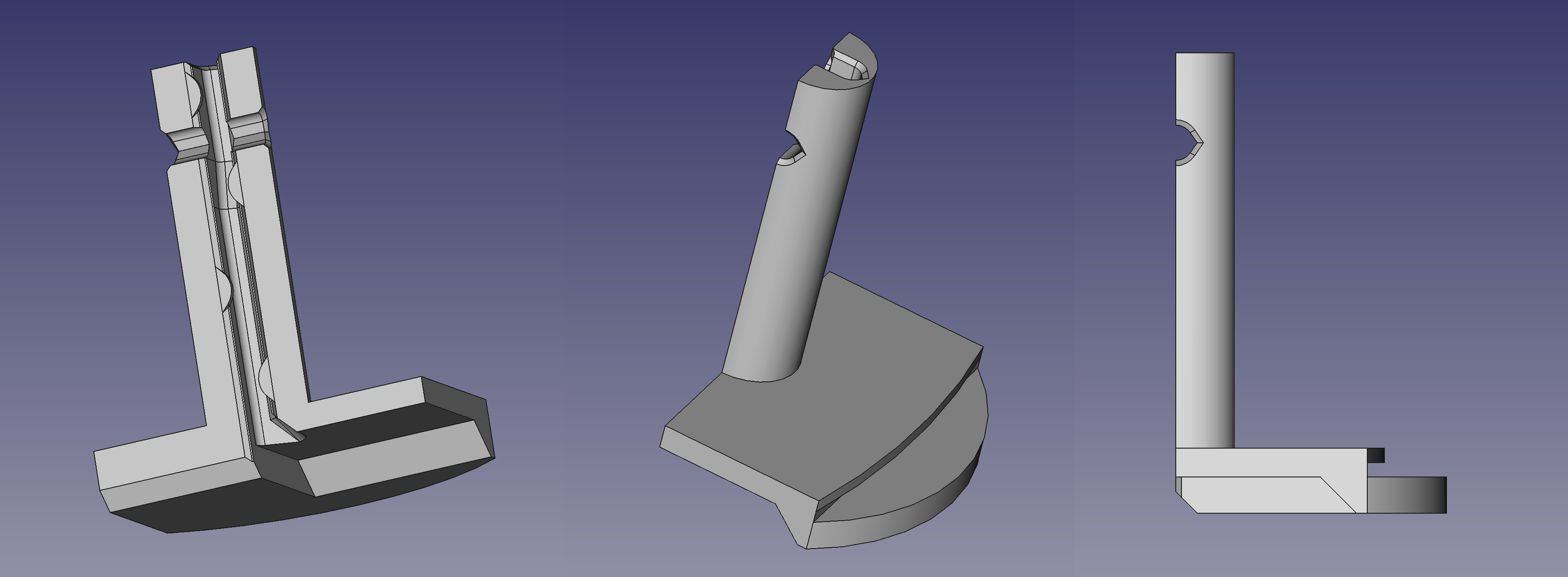
- The main axle now consists of two mirrored parts, split lengthwise along the axle. This way they can be printed lying down for maximum strength.
- Each part of the axle has a groove that fits a 1.2 mm lead. The groove gets gradually deeper along the upper part of the axle.
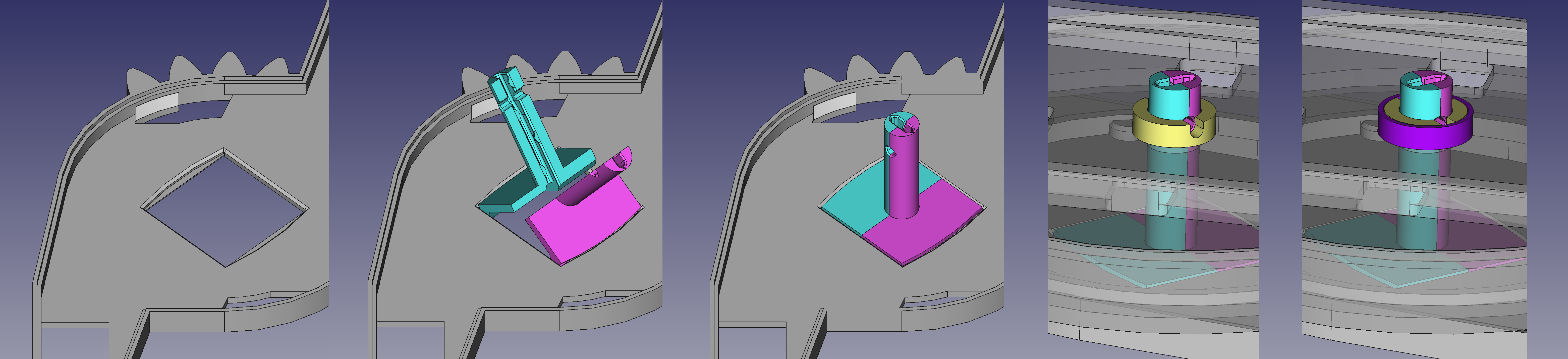
- The base of each axle part has a slot that fits the edge of the rectangular cutout in the lower body. The parts gets attached by folding them into the cutout.
- To pin the axle to the upper body, a short length of 1.75 mm filament is slid horizontally through the axle, between the two leads, and is held in place by a 3D printed ring nut.
- A thin sleeve is fitted over the assembly to prevent the filament from sliding out.
- The PCB fits snugly on top, which in turn prevents the sleeve from getting loose.
Discussions
Become a Hackaday.io Member
Create an account to leave a comment. Already have an account? Log In.