 Canine Defense Technologi
UAV Assembly & Integration Summary
It's been a busy few months of in-house fabrication and chatting with some contractors who took care of machining and SLS 3D printing, but the parts are finally in the Lab and being integrated into the UAV assembly for assembly! Even during assembly, there were dozens of part design modifications and iterations pushed in CAD for a truly data-driven workflow. Below are some of the highlights of the now-integrated hardware!

View of the partially complete airframe during integration with dummy development optic pod placeholder
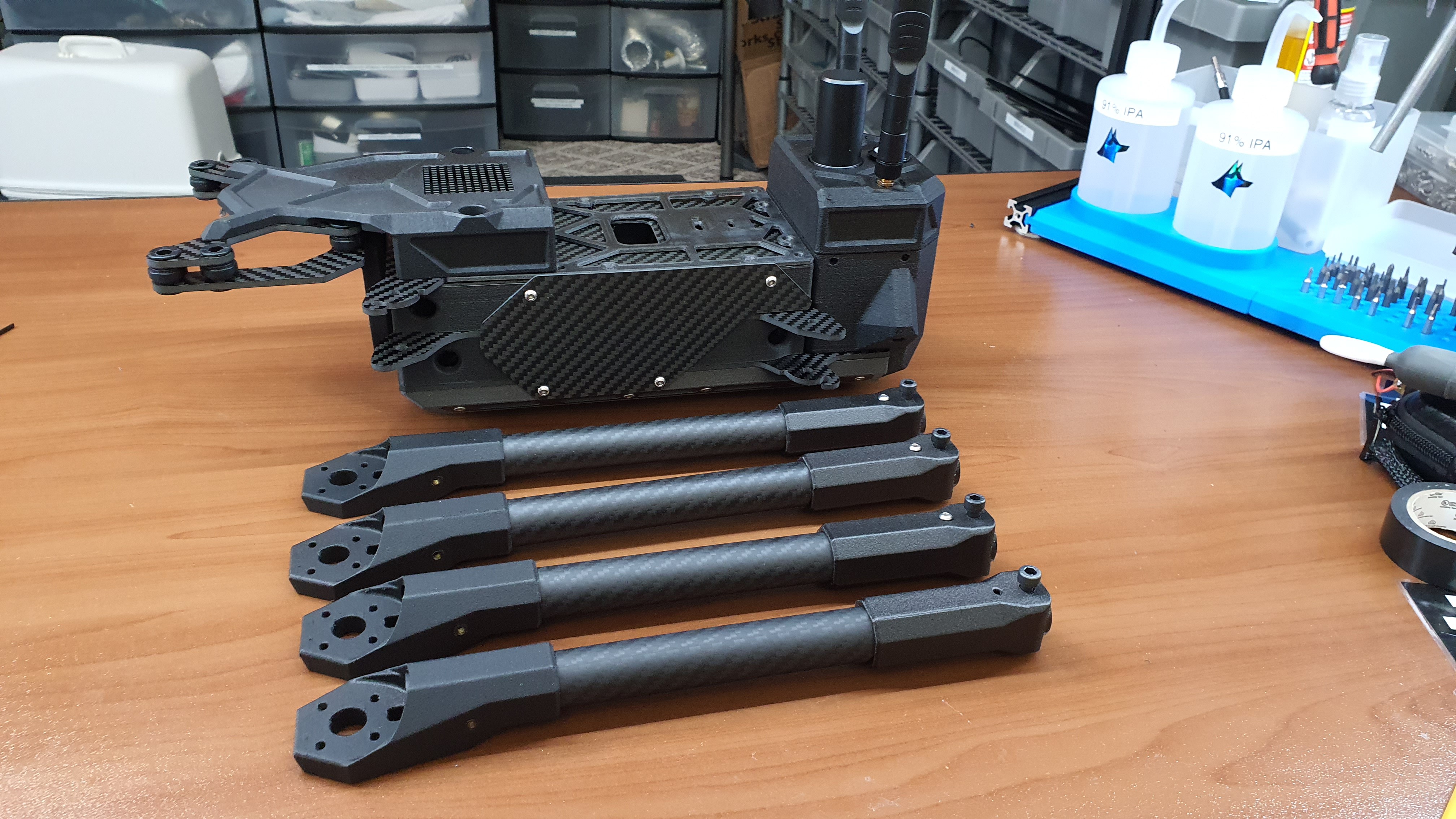
View of arms and airframe body before integration

Machined side payload rail
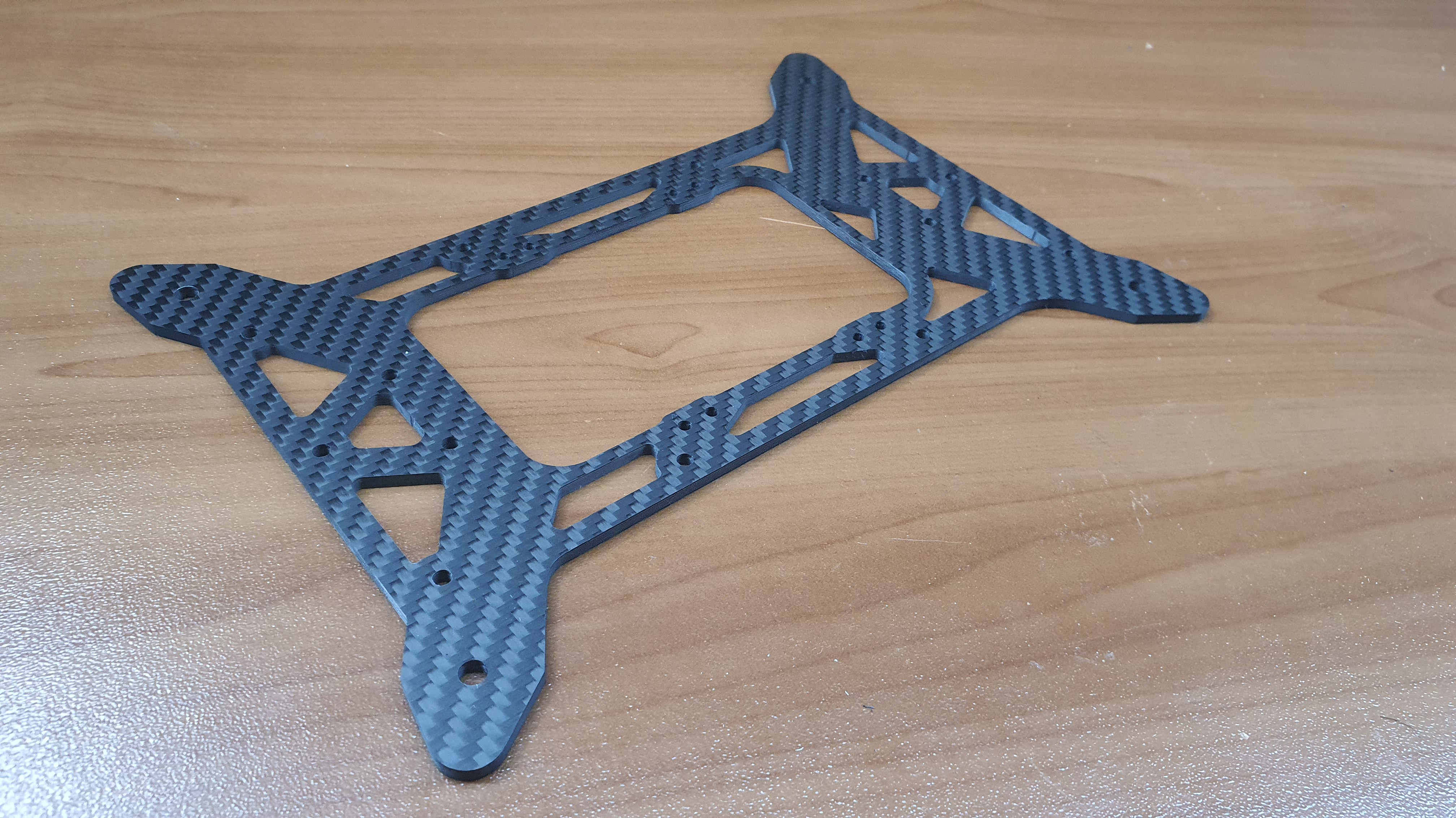
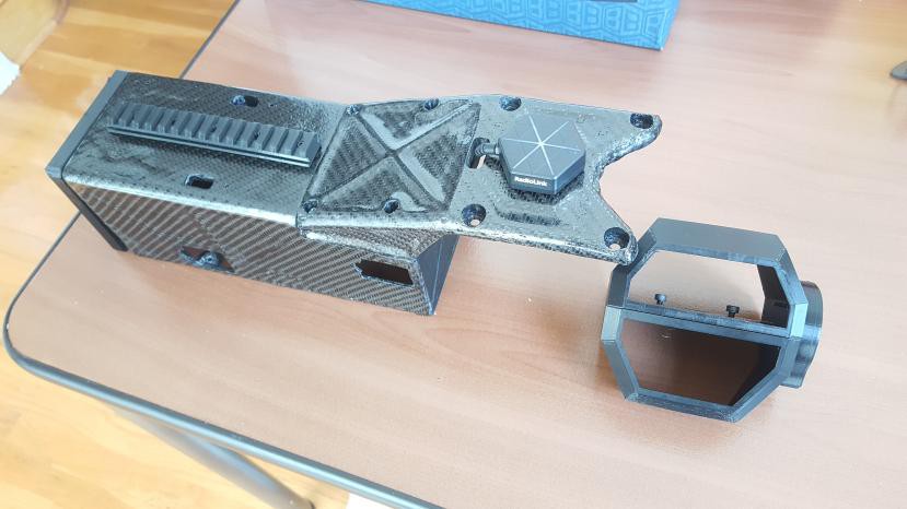
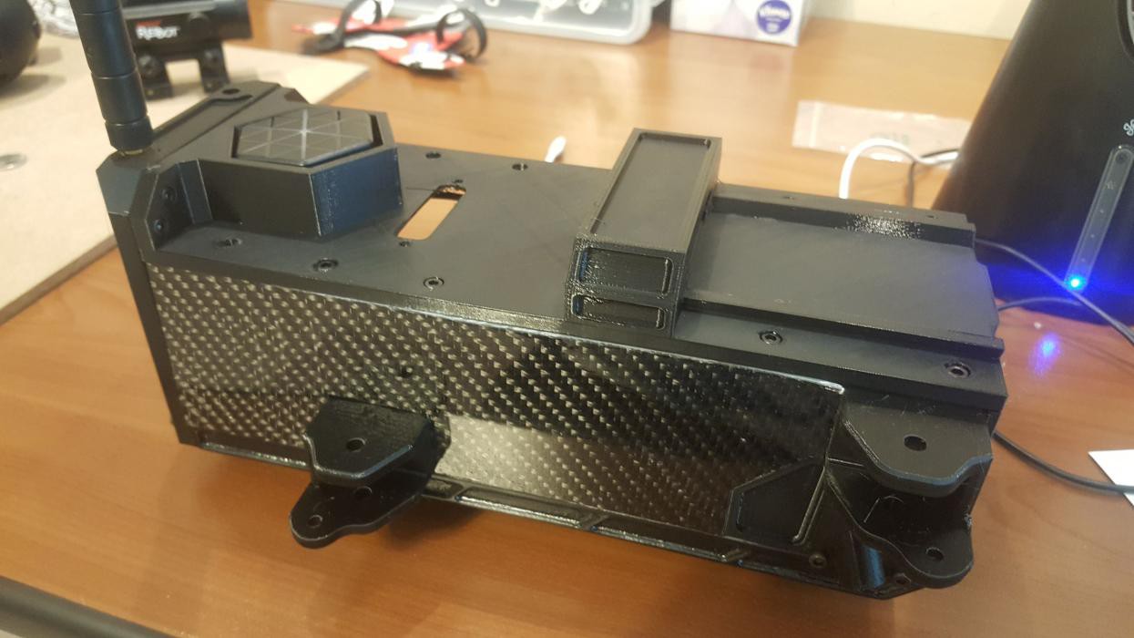
View of Central Carbon Fiber Structural Airframe
View of Universal Payload Interface Plate
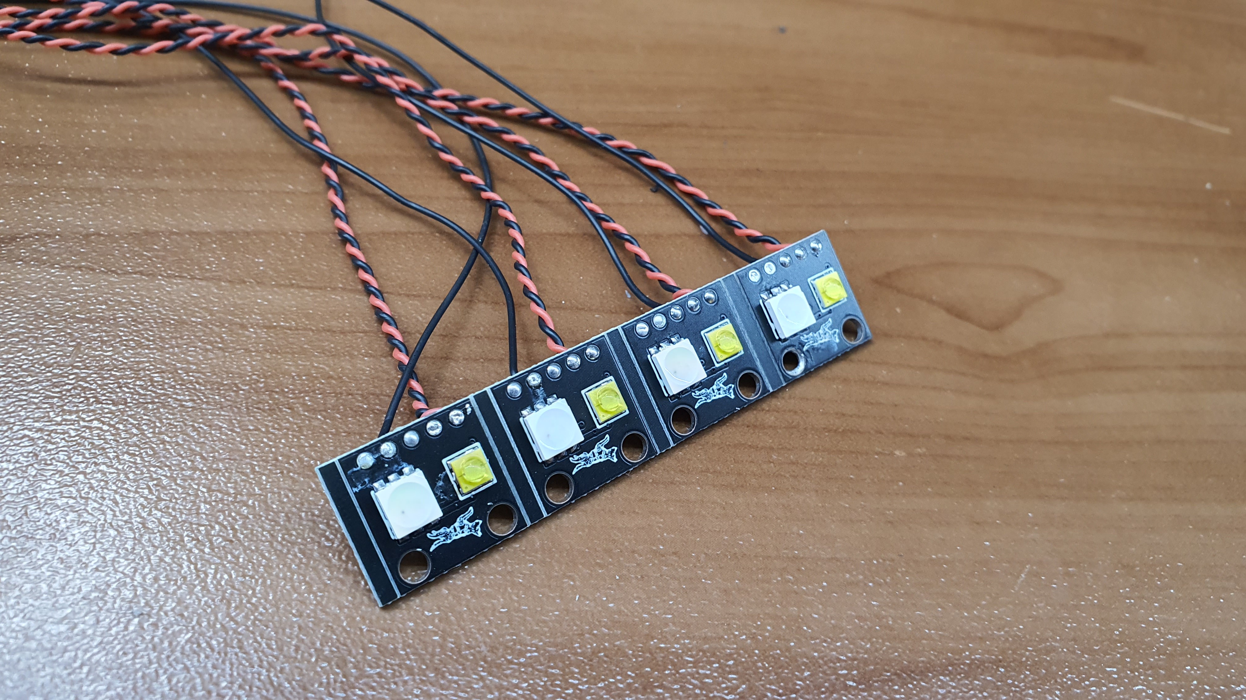
View of custom Nav Light PCBs. Integrated RGB and super right white strobes!
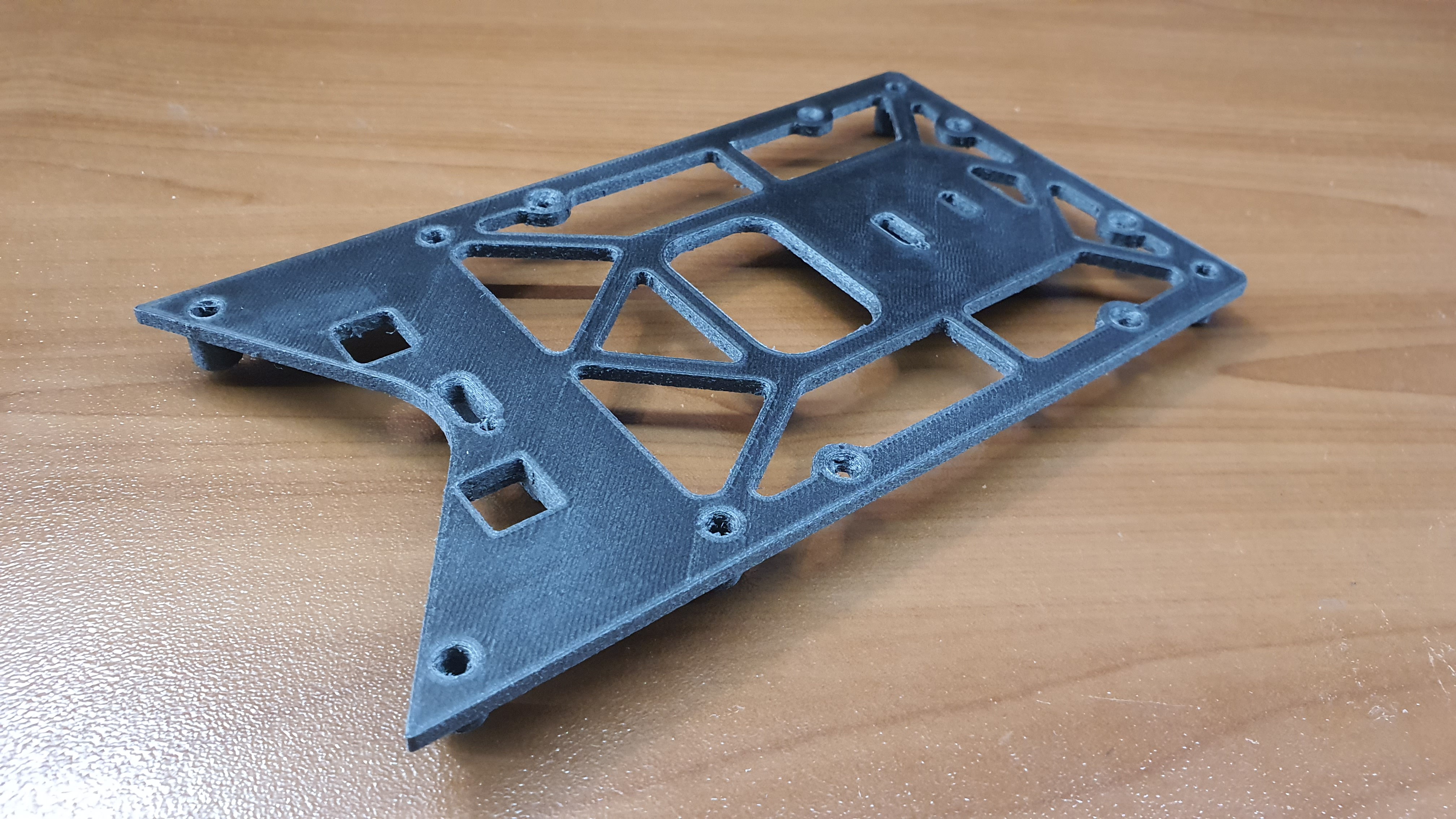
View of 3D printed airframe piece
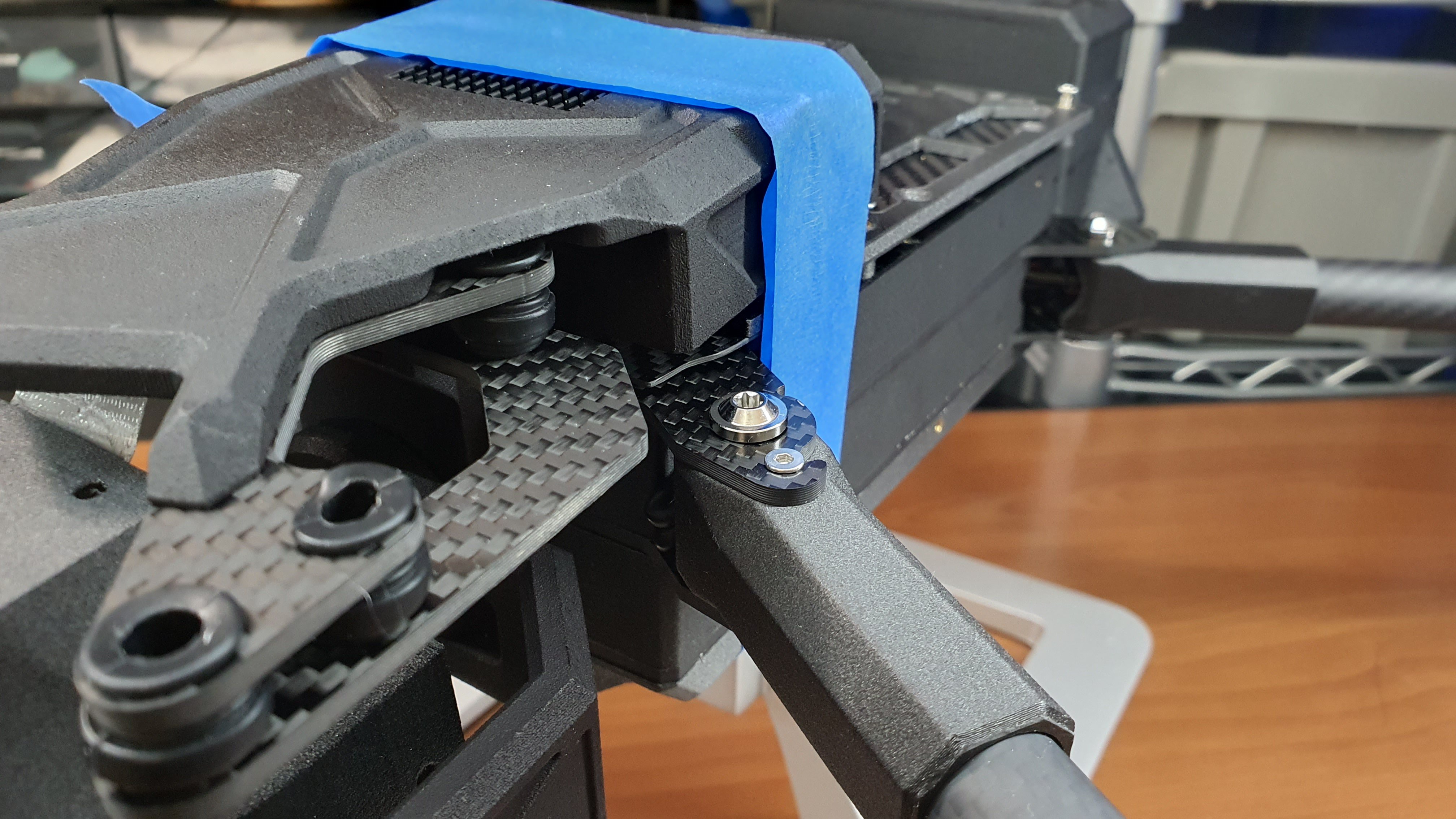
Closeup view of arm assembly
Iterative Design, Material Selection, & Tight Mass Budget
One of the primary design challenges with Valor was balancing out durability, mass savings, and end-user easability. Often times decreasing the mass of the overall structure leads to comprises in durability. Every extra end-user easability feature is added mass that doesn't contribute to flight performance or flight time. All in all, the design requirements appear conflicting, but with careful consideration of material selection and design, the overall goal was achieved. There were simple measures such as switching all hardware fasteners from stainless steel to titanium. That measure alone shed off the weight of fasteners in the totality of 20%, an impressive figure. But this 20% mass shaving is a small save since the overall mass of fasteners is marginally small compared to the entire airframe, in comes the most challenging comprises.
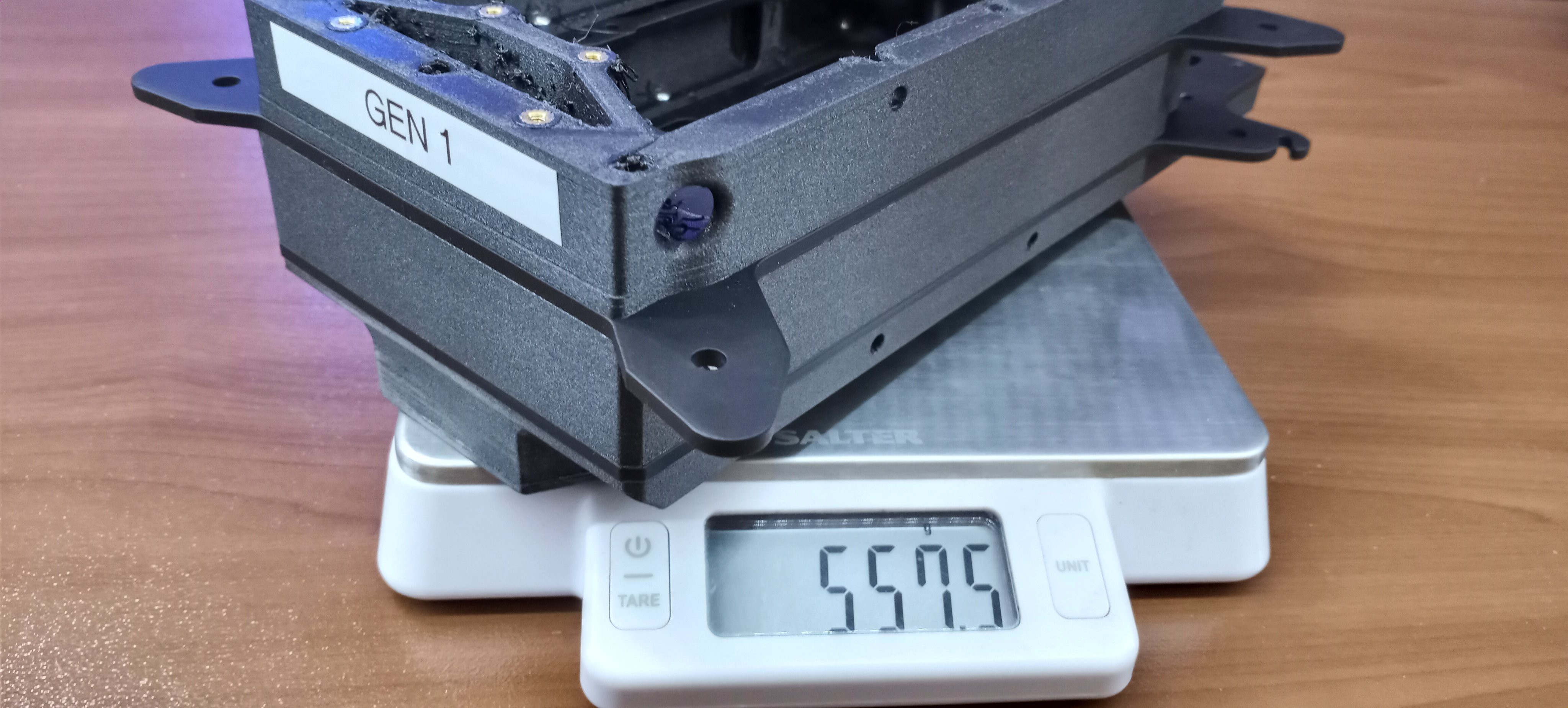
Initially to save weight we went with a "Exoskeleton" approach, a single 3D printed ariframe that would be skinned in carbon fiber. All the structural component were built into a single large body, including the SPOT optic pod. The critical flaw with this approach was the fact every component was permanently fixated together. In the case of a crash, a single component damage would require the entire airframe to be rebuilt. Not only that, modularity was severely comprised since essentially the entire UAV by and large was a single piece.
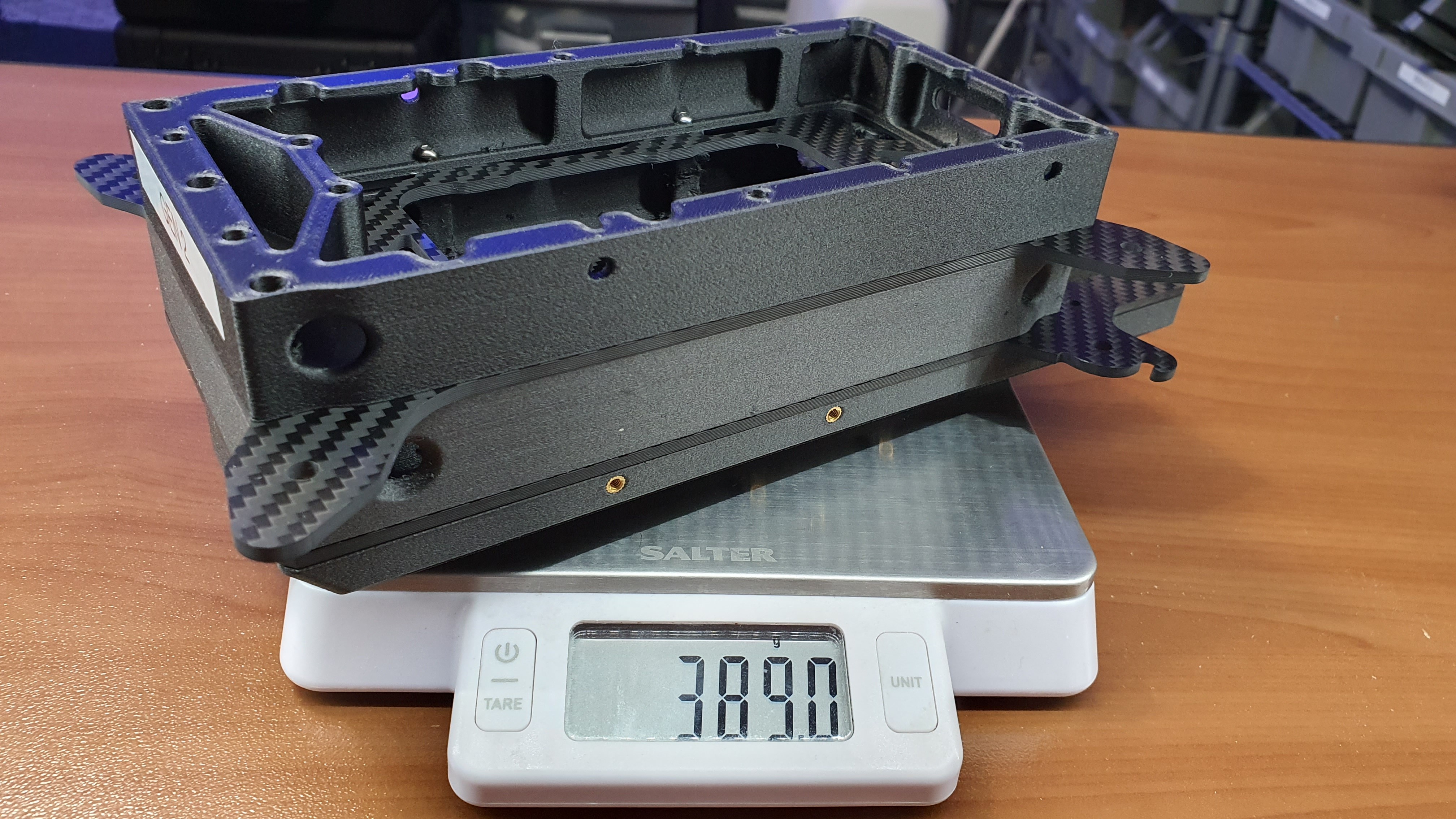
The V2 was much closer to what we settled with, multiple small modules that would assemble into each other. The problem with this approach was the strange angles gaps produced by the geometry of each module. This made effective waterproofing practically impossible (more or less highly impractical). The primary reason V2 was scrapped was the lack of stuctural integrity. Each arm joint was its own singular piece, and being FDM 3D printer, it was far too flexible to be an effective structural component.
View of V1 airframe, a single piece design. In this version SPOT was going to be permanently mounted into the drone!
View of V2 airframe. Much closer to V3, but still had many limitations and shortcomings structurally.
Now the focus for V3 shifted to structural integrity. Modulairty, waterproofing, and weight are all important attributes, but essentially useless if the airframe can't take any loads in flight or in transport. In the design of V3 is alll came down to frame design and material selection. By making a stacked design, waterproofing was easy and naturally strcutual integrity was maximized. The clear winning material for strength and durability, one of the attributes of Valor sUAS we were aiming for, was alumnium. It checked off everything we were looking for except in mass. It was the singular source of bankrupting our mass budget. The switch to carbon fiber along with optimized print settings was the solution. We were shocked by how much weight we cut out with this simple change
View of extremely durable (But far too heavy) aluminum airframe dev prototype.
View of much lighter Carbon Fiber Airframe
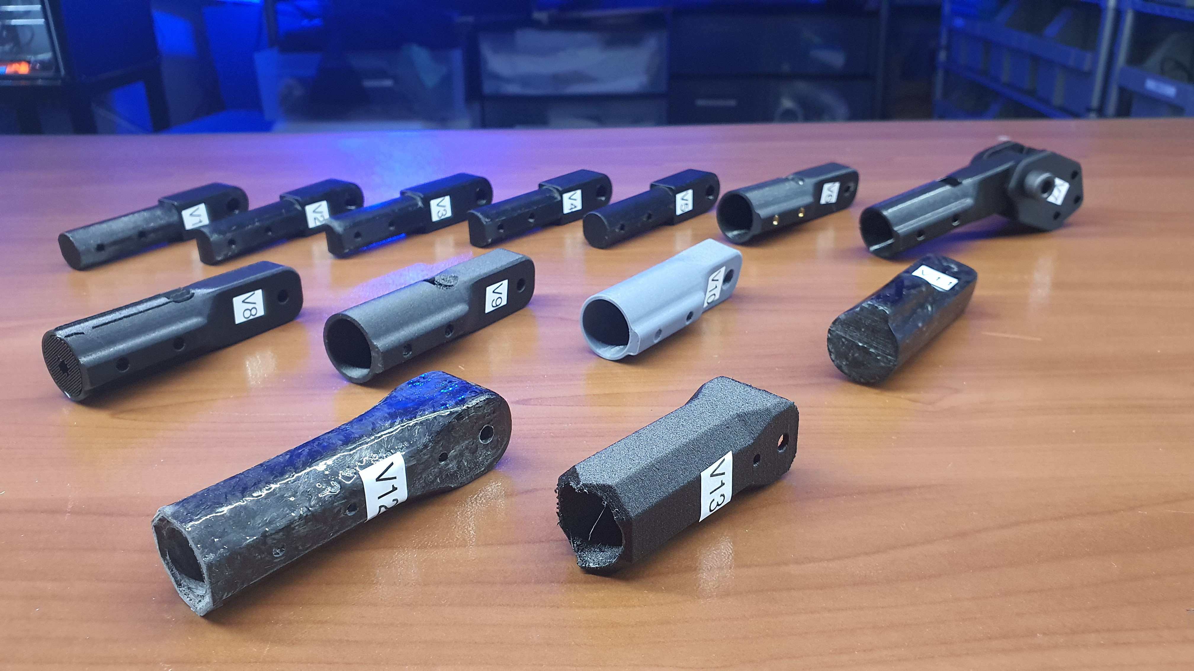
View of locking arm bracket iterations
The airframe was obviously a massive engineering challenge on its own, but no other part went through more iterations than the locking arm joints. The original arm joints were fully 3D printed, far too weak for the massive motors and props producing several kilograms of thrust and sending it straight into its joints, not to mention the multiplication of the load because of the moment the long motor arms create. The test phases for the arm joints were unintentionally very destructive and very stressful, the mid conclusion was that it would be impossible to achieve success without using stronger materials. We explored machining it out of metal to even SLM printing it out of metal, all very expensive solutions that would have led to the same bankruptcy of our mass budget. We were making the same mistake as we did with the airframe. The solution was much like the airframe, switch over to carbon fiber. But it would not be a typical layup but rather forged carbon fiber; use 3D printed molds and compression form a resin-chopped carbon fiber matrix. It worked really well, with one issue; the painstaking post-processing and matching required. It was simply not worth the effort.
At this point the realization came that the issue was not the material, it was the design of the bracket. The final flight version of the locking arm ended up being 3D printed after all, but it doesn't bear the brunt of the massive load as the previous versions did. With a very simple rudimentary design change, all the load is transferred into the already strong carbon tubes and airframe. All without a chunk of layer-by-layer molded plastic ready to snap at not even a quarter of the load it would experience in flight.
Discussions
Become a Hackaday.io Member
Create an account to leave a comment. Already have an account? Log In.