Close
0%
0%

A Retro-Authentic Microtronic Emulator

Compute like its 1981 - hex on a 6digit 7segment LED bubble display!
(One of the) RetroChallenge 2021/10 "Winners"

Similar projects worth following
Another take on my Arduino-based Busch 2090 microtronic computer system emulator - compute like its 1981! Key in your machine code in hex and enjoy the retro-authentic 7segment LED bubble display.

**My #retrochallenge @retrochallenge 2021/10 entry - check out the logs for updates!**

My #retrochallenge @retrochallenge 2021/10 entry - check out the logs for updates!

https://www.retrochallenge.org/p/entrants-list-202110.html

A follow-up on

https://hackaday.io/project/176466-microtronic-the-next-generation

and

https://hackaday.io/project/11560-the-talking-microtronic-computer-system-emulator

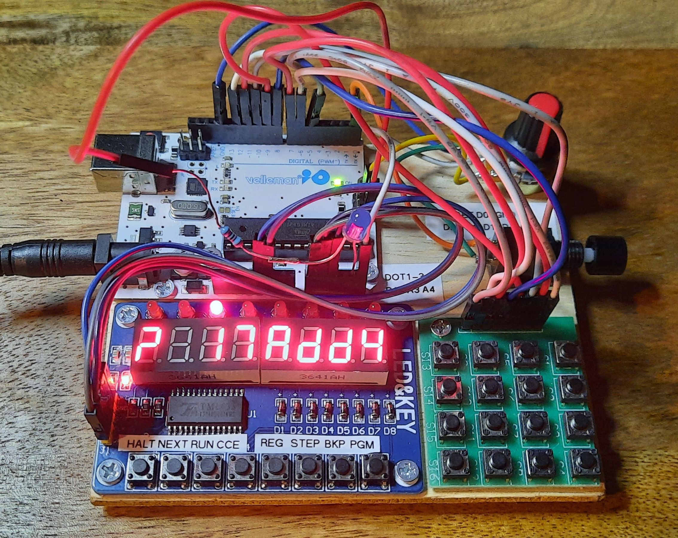
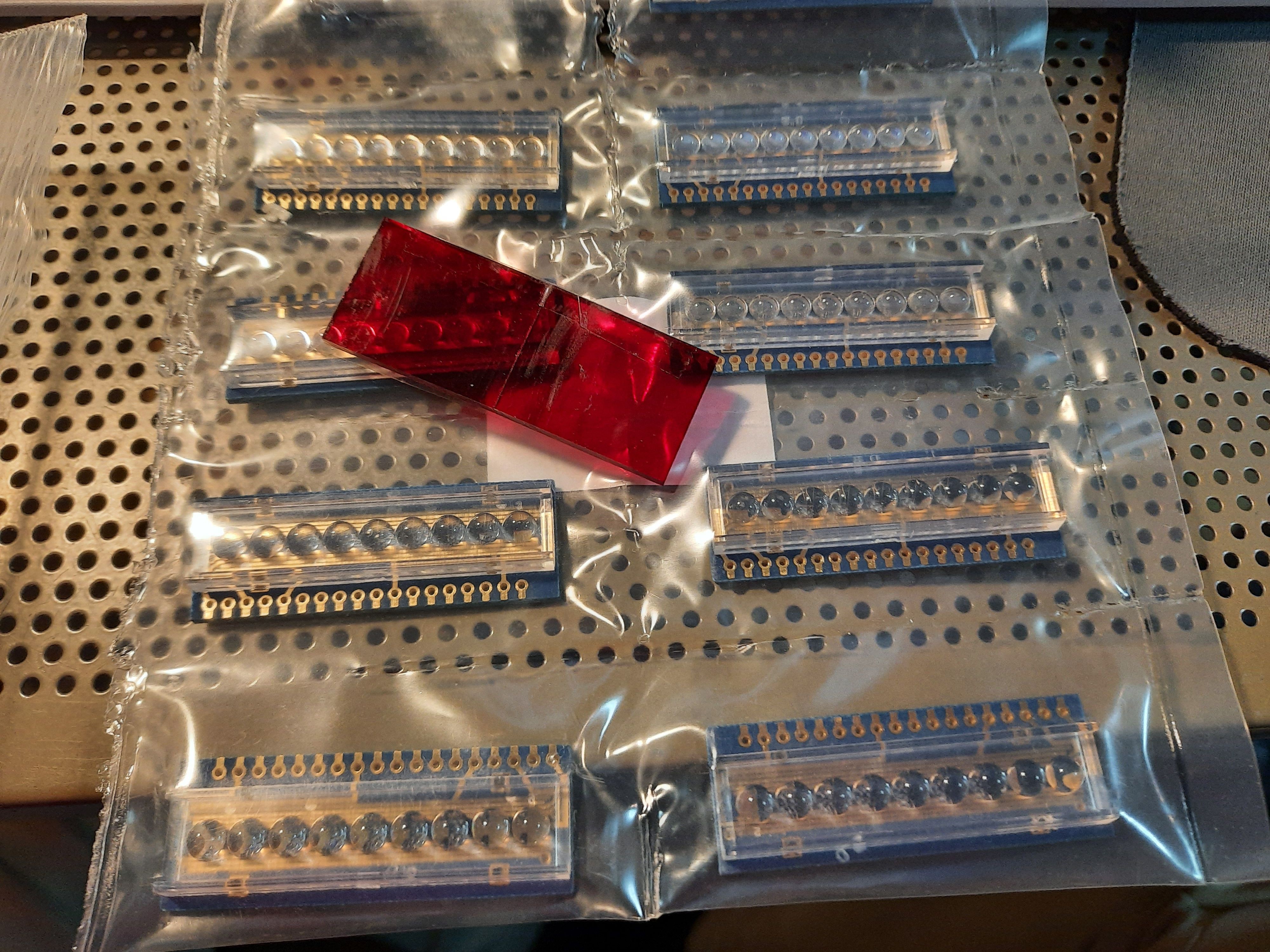
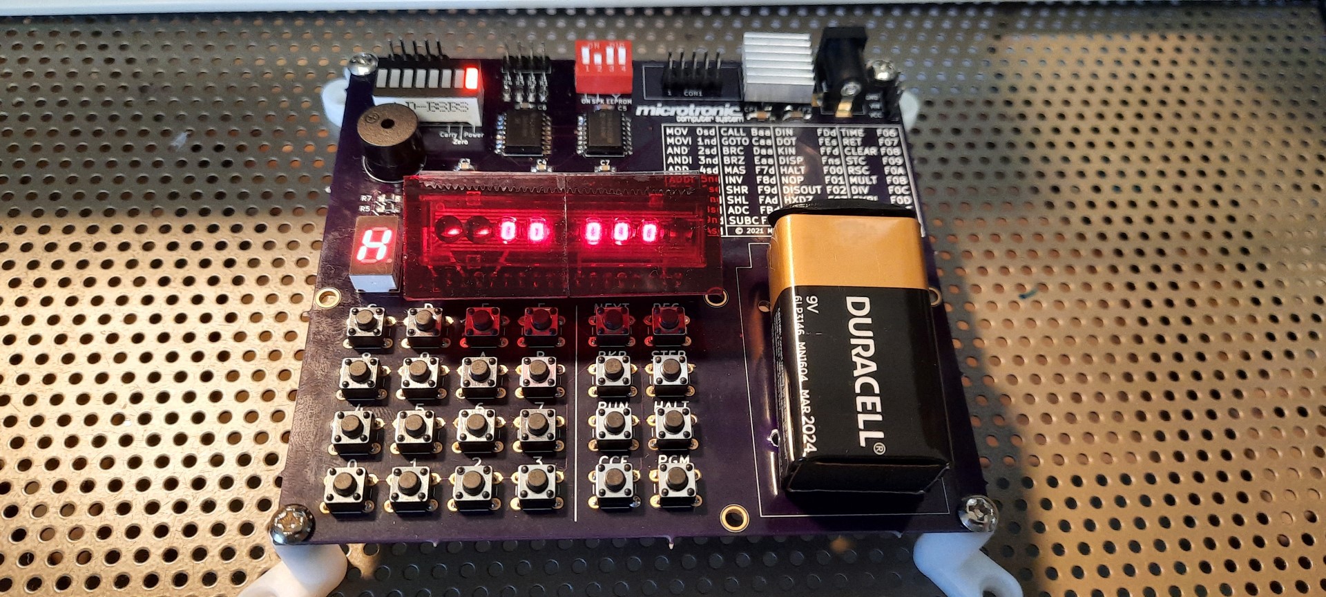
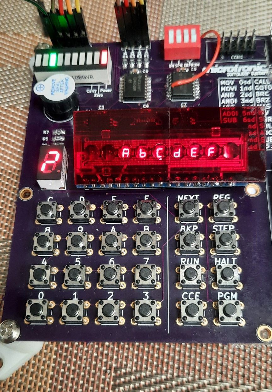
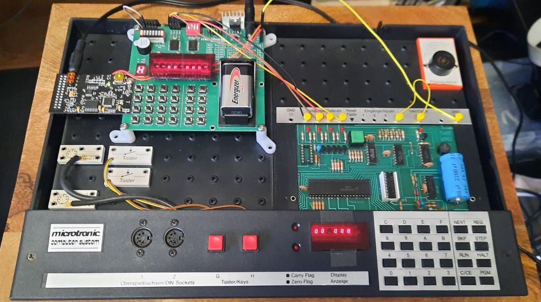
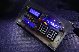
I found these adorable 6digit 7segment LED bubble displays which are very close to the ones used in the original Microtronic from 1981. I couldn't resist and had to make yet another version of my Microtronic emulator.

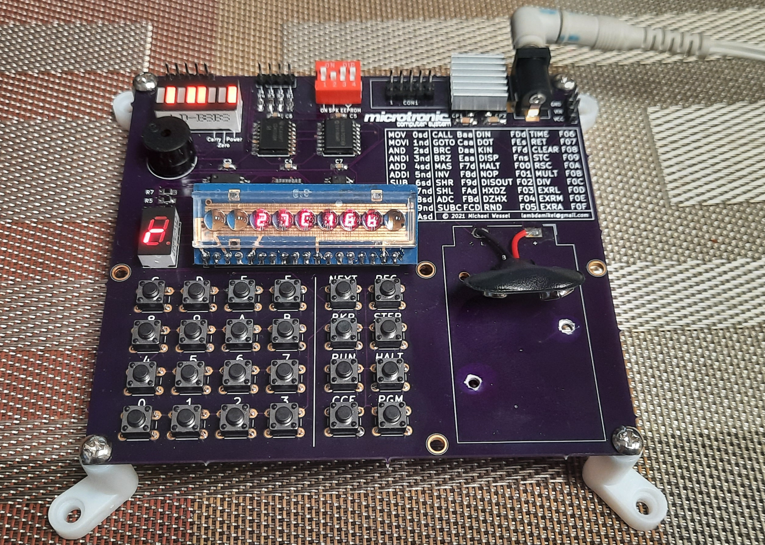
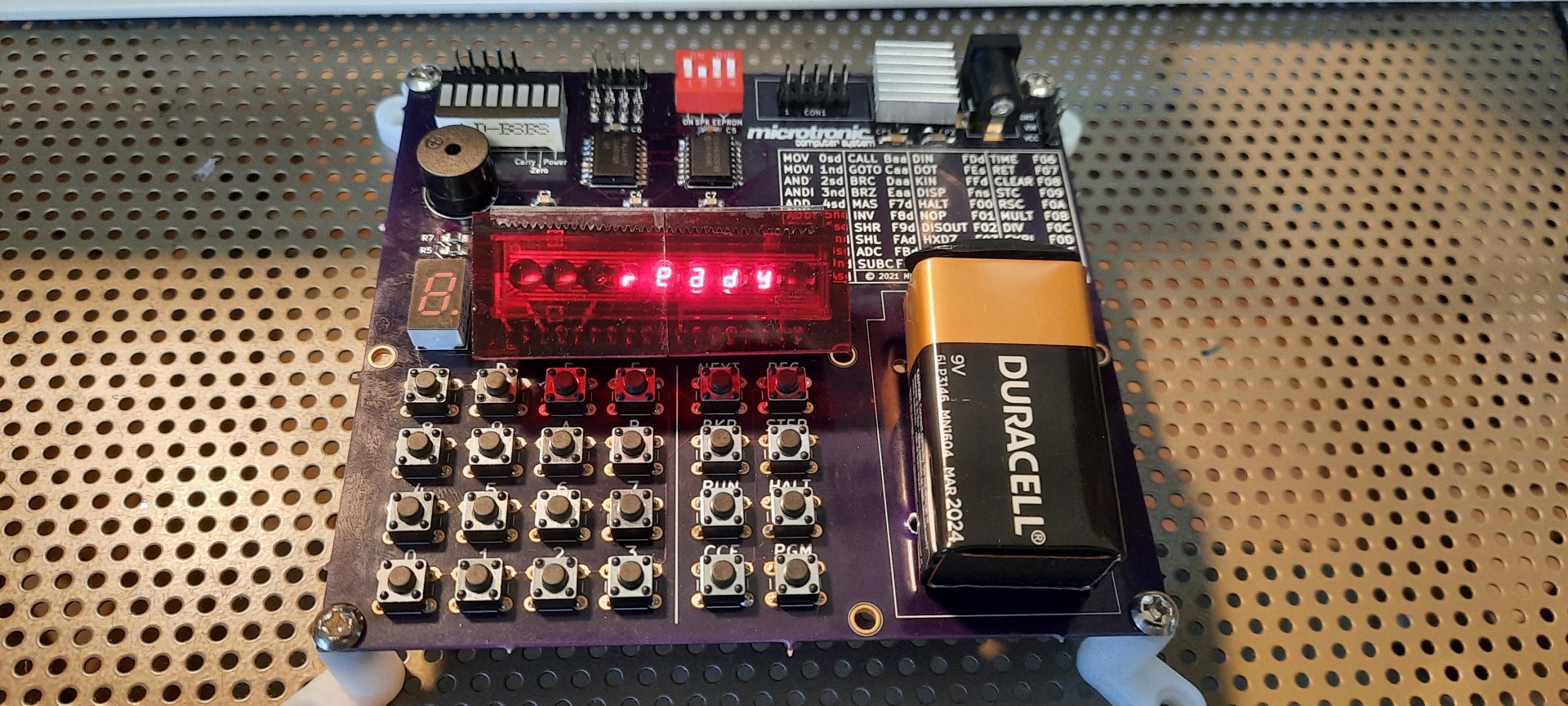
This time, the experience is 100% retro-authentic. The only difference over the original is that I have a blinking LED "cursor" in the display. Another goodie is the use of an EEPROM for program storage.

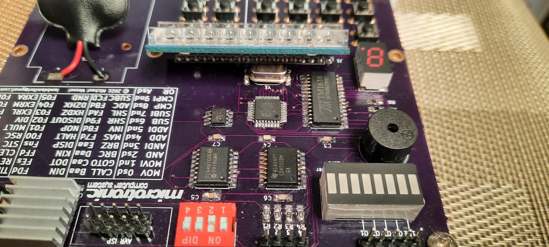
This is the first SMD PCB I ever made; I still need to improve my SMD soldering technique a bit, but it works! 

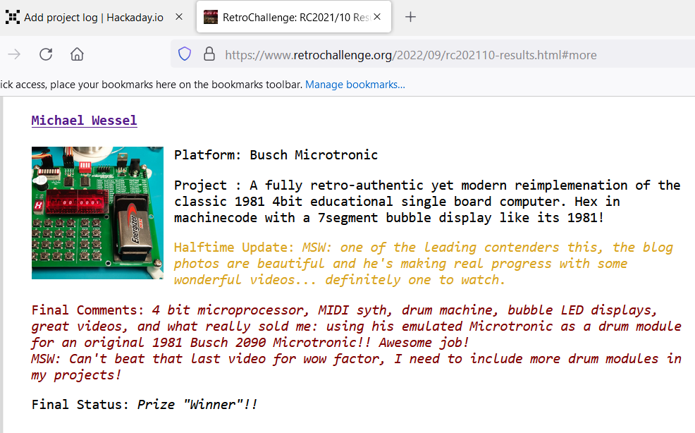
Final RetroChallenge 2021 / 10 Update:

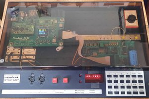
Let's wrap up my RetroChallenge 2021/10 contribution by demonstrating the original 1981 Microtronic, and how IT plays the drums, using the Microtronic emulator as its "drum module":

https://hackaday.io/project/180252-a-retro-authentic-microtronic-emulator/log/199810-retrochallenge-retrochallenge-wrap-up-finale-update-6

Previous updates: 

https://hackaday.io/project/180252-a-retro-authentic-microtronic-emulator/log/199133-retrochallenge-retrochallenge-update-4


Older Videos, not RetroChallenge related:


This demo features action games, and higher math:


Schematics:


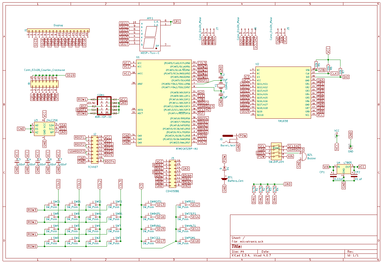
(There is also a PDF version of the schematics in the files section here).


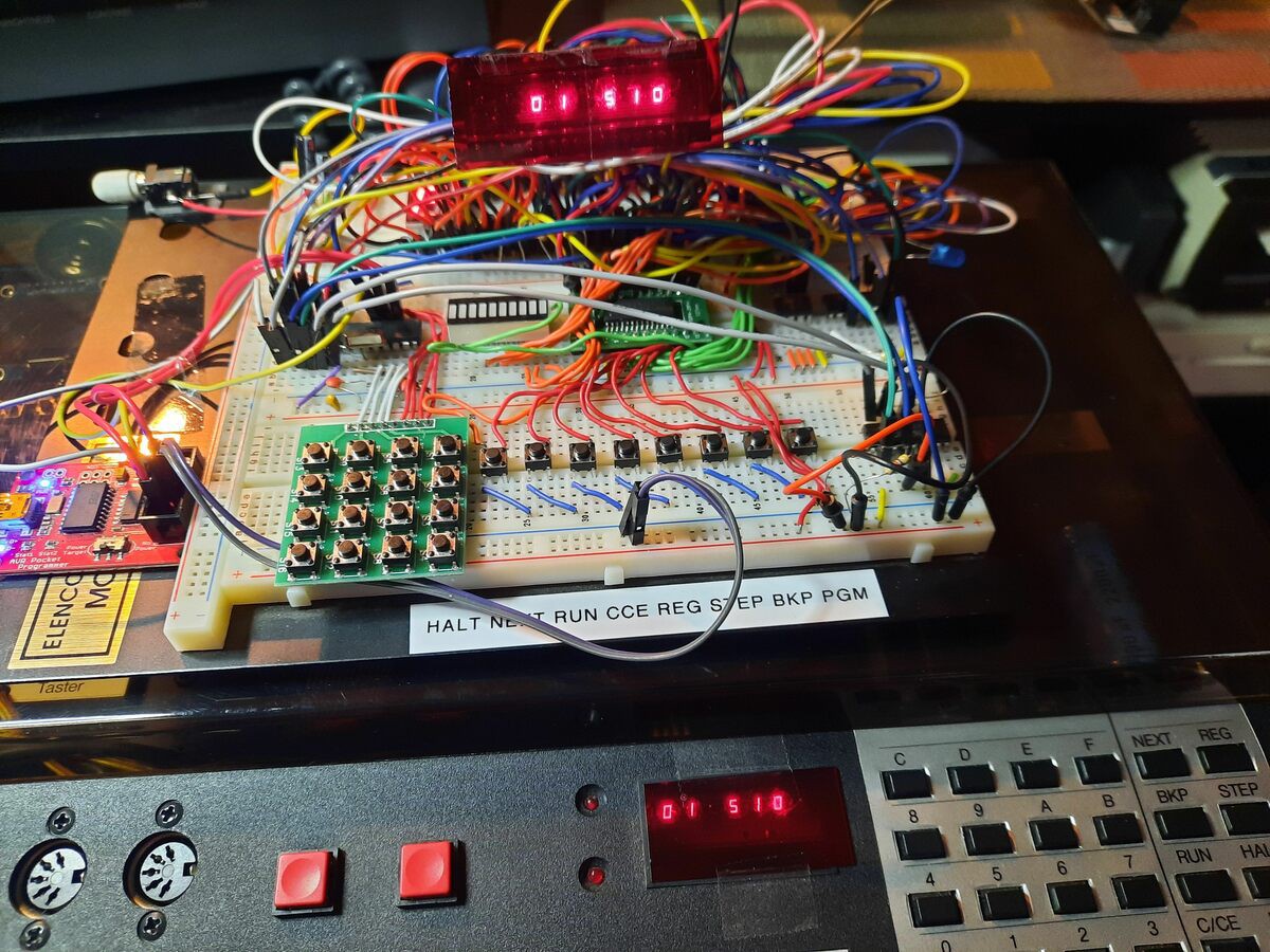
It started as an Arduino Uno R3 project in 2006: 

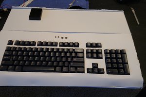
Then I re-engineered the "LED&KEY" module and acquired a number of TM1638 chips. Since they are only available as SMD, I had to bite the bullet and learn how to SMD solder. The result was a breadboard with one SMD chip (the TM1638) on a DIP carrier board: 

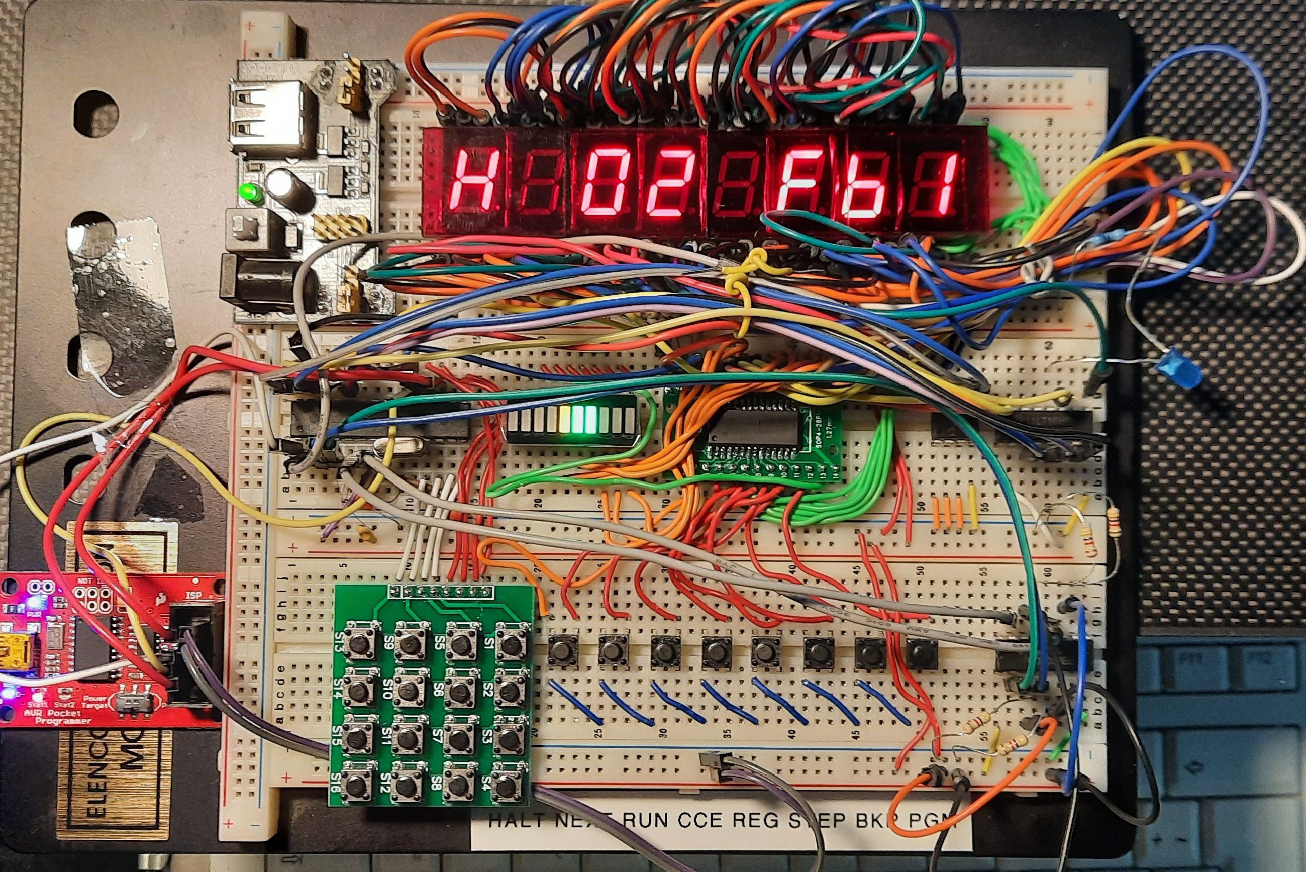
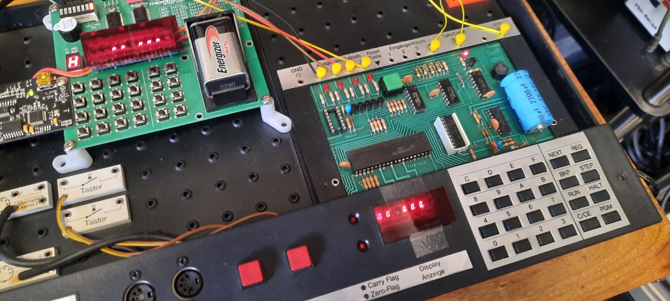
Then I discovered the adorable 6segment LED bubble displays and realized that I could create an emulator with a very authentic look & feel: 

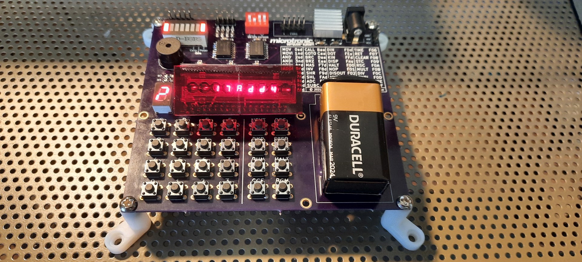
This evolved into the SMD PCB you are seeing:

x-zip-compressed - 134.41 kB - 06/17/2021 at 14:55

Download

Adobe Portable Document Format - 153.73 kB - 06/17/2021 at 14:55

Preview
Download

busch2090-pcb.ino

Arduino Uno R3 / ATmega 329p @ 16 Mhz sketch.

ino - 38.71 kB - 06/09/2021 at 19:08

Download

  • The RC 2021/10 results are in - and Microtronic Drums are a winner!

    Michael Wessel09/07/2022 at 04:30 0 comments

    https://www.retrochallenge.org/2022/09/rc202110-results.html#more

    Well, it took a while for the RetroChallenge 2021/10 results to come out, but  here they are! The Microtronic Drums are one of four "Winners" - even though the RetroChallenge is not really about "winning", but the fun of participation and the projects themselves, it's nevertheless nice that the project got recognized - thanks to the organizers for this!

  • #RetroChallenge @RetroChallenge Wrap Up / Finale / Update 6

    Michael Wessel10/30/2021 at 16:56 0 comments

    To wrap up my 2021/10 RetroChallenge contribution, I wanted to use the opportunity to demonstrate the real Microtronic to you, and how IT can play the drums!

    So this is the original from 1981 that I am emulating; note how the retro-authentic emulator (top left corner) is hooked up to it via 4bit GPIO connection: 

    Can it play the drums, too? Yes it can!

    The original Microtronic uses a TMS-1600 masked-programmed microcontroller, clocked at 500 kHz. There is no EPROM or the like, hence making is impossible for me to hack the firmware / monitor to add "MIDI support" to the instruction set as I did for the emulator. The original TMS-1600 Microtronic firmware is not available, and what's worse, it is not straight-forward to read out the content of the mask-programmed microcontroller ROM!

    I wish they had used an extra ROM or EPROM for the firmware / monitor program, but that would have driven up the price quite a bit. After all, the TMS-1600 is a microcontroller, not a CPU, and not requiring all the additional chips was and is a major selling point for microcontrollers. TI marketed the TMS-1000 series as "computers on a chip". The TMS-1000 series were the first microcontrollers available on the mass market. Flash memory probably didn't even exist back then, so Busch probably had to sent a tape containing the ROM mask to Texas Instrument in 1979 / 1980.  I guess Texas Instrument "programmed" these chips directly in the factory (were other companies besides TI capable of doing this? not sure). At one point I also checked with TI support if they would have the mask files in the archives somewhere, but to no avail of course. I had no success with Busch either.

    I was debating with myself the idea of sending a Microtronic TMS-1600 to Sean Riddle who decapped a number of TMS 1000-based MCUs and extracted the ROMs (!), e.g., from the SIMON game, as well as a number of TI calculators. But I haven't convinced myself yet that I want to sacrifice one of these ultra rare chips. Decapping is obviously a pretty destructive process, so I haven't reached out to Sean yet. AFAIK, Sean even has a TMS-1100 emulator. It would be awesome if one day the original Microtronic firmware was running on an emulator such as mine! After all, my Arduino emulator firmware was written be hand, by re-engineering the instruction set and the monitor program, with no knowledge of the original firmware program. Which of course also made extending it (as demonstrated here, for MIDI support and what have you) much easier. And I certainly prefer Arduino and C over TMS-1100 assembly... the TMS-1000 has a VERY interesting architecture, check it out. Things have changed quite a bit since these early days! Programming TMS-1000 assembly would be an interesting challenge in itself! Luckily, I didn't have to do that.

    So, back to the drums. To make the original Microtronic play the drums, we cannot connect the X2 MIDI module directly to it. It is impossible for it to generate MIDI data with its limited resources (31250 BAUDs? are you KIDDING ME?) However, we CAN hook it up to the emulator using GPIO, which can then act as a drum module for it. Hence, I am simply using the Microtronic's GPIOs. The Microtronic is sending the 4bit drum number to its digital outputs, and 4 cables + 1 GND transmit that to the digital inputs of the emulator, which simply samples the port as fast as possible, in a loop, and whatever it reads it outputs to MIDI. As simple as that.

    Now, that's of course only possible because we have the 0 drum  which means "no sound".  Note that there is no common clock signal between the two, so this is purely asynchronous communication, with all its problems. But it works!

    On the Microtronic side, the transmit program is the following; it simply steps through all the drums from 0 to 15: 

    # display register 1
    00 F10
    # add 1 to register 0 
    01 510  
    # output register 0 to digital outputs 
    02 FE0
    # move 0 into...
    Read more »

  • #RetroChallenge @RetroChallenge Update 5

    Michael Wessel10/21/2021 at 18:44 0 comments

    In this episode, we are making the drum computer 3-channel polyphonic!

    This requires some major rewrite and additional op-code side effect extensions. The 2x 16 registers obviously aren't enough for a 3-channel polyphonic 16 step sequencer, so we added some extra 3x16 array memory to the emulator. The registers R0 and R1 are used as index / address registers for the array memory. In fact, R0 would have been sufficient for 16 positions, but the array memory could be larger if I only had more SRAM available, at least conceptually ;-) 

    To work with the new array memory, I equipped a number of vacuous ANDI op-codes (3Fx) with extra side-effects to provide R0, R1 index increment, load from the array at the current index into Microtronic registers, and store Microtronic registers back into the array memory at the current index positions. Three registers are loaded / stored at the same time with one instruction (the array has shape 3x16).

    Note that the official effect of the 3Fx op-code is to perform a bit-wise AND of 0xF with register x, which is idempotent for 4bit registers, so no program would ever use any of these 3Fx op-codes.

    The new side-effects for ANDI with F are:

    • 3F5: load array at location R0, R1 into R5, R6, R7 
    • 3F6: store R5, R6, R7 into array at index R0, R1 
    • 3F2: increment array index R0, R1 (to prevent boiler plate code) 

    Drum computer code:

    # 3 voice polyphonic drum computer 
    
    00 022
    01 3f1
    02 f44
    
    # r0, r1 are array memory index registers (currently, only r0 matters - 16 steps)  
    # reset index to 00 
    03 101 
    04 100
    # use r4 to display current index on display (copy from r0) 
    05 104
    
    # load current array memory content at r0, r1 index into r5, r6, r7
    06 3f5 
    # DIN input into rE - put HI on DIN 1, 2, 3 for channel select! 
    07 fde  
    
    # channel 1? 
    08 91e 
    09 e0f
    # channel 2? 
    0a 92e 
    0b e14 
    # channel 3? 
    0c 94e 
    0d e17     
    0e c18
    
    # input channel 1 -> non-blocking KIN into r5
    # use NOPs so that all branches take equal number of clock cycles 
    0f ff5
    10 f01
    11 f01
    12 f01
    13 c18
    
    # input channel 2 -> r6
    14 ff6
    15 f01
    16 c18
    
    # input channel 3 -> r7
    17 ff7
    
    # output r5, r6, r7 MIDI drum numbers to MIDI output 
    18 055
    19 066
    1a 077   
    
    # store current r5, r6, r7 values back into array memory 
    1b 3f6 
    # increment array memory index / address (r0, r1) 
    1c 3f2 
    # output r0 index to DOT 
    1d fe0 
    # copy r0 index to R4 so that we can see it on the display 
    1e 004 
    # loop 
    1f c06

    Here is a video of the drum computer in action: 

  • #RetroChallenge @RetroChallenge Update 4

    Michael Wessel10/17/2021 at 16:59 0 comments

    In this episode, I extend the pattern-based drum computer to full 16 steps / beats (4 bars x 4 beats),  and tailor for real time drum pattern input (like a real drum computer).

    This requires inputting data from the keypad using the KIN (Keyboard Input) op-code, whilst playing back the pattern, and hence isn't possible with the standard Microtronic KIN. Thus, I implemented a non-blocking KIN behavior. Utilizing 2 more vacuous op-codes, I can now toggle between the standard blocking KIN input behavior, and the new non-blocking behavior.

    The op-codes for determining the KIN mode of operation are 3F0 (blocking KIN mode) and 3F1 (non-blocking KIN mode). By default, the Microtronic only uses blocking KIN. The vacuous op-codes 3F0 and 3F1 are idempotent immediate AND (ANDI) op-codes, i.e., the operand 0xF = 0b1111 = 15 is idempotent for 4bit registers, and hence, no (existing or new) program would ever use them. So it is safe to assign the mode toggling extra side-effect to them.

    In general, the following vacuous op-codes are available for side effect extension:

    • MOV x,x: copy register x onto register x, 0xx
    • ADDI 0,x: add 0 to register x, 50x
    • SUBI 0,x: subtract 0 from register x, 70x
    • ANDI F,x: bitwise AND of register x with F, 3Fx

    I have used a few of these by now for various side effects (e.g., play the MIDI drum in registers 4 to 7 via 044, 055, 066, 077; enable MIDI output 022, and so on). It is good that I have so many vacuous op-codes available, and it is interesting to find a good "balance" and clever allocation of extra side effect semantics to those that would be most useful for programs. Obviously, this is currently driven by the needs of the drum computer program. But in a future project, these could be used for different purposes (e.g., to drive a text character display, a speech synthesizer, or what have you).

    Moreover, given that we now have 16 beats in the drum pattern, we need register memory to store these based on user input, and I am explaining how to utilize the Microtronic's Extra Register Set to help accommodate them.

    The Microtronic has 16 foreground and 16 background (or "extra") registers, and they can be exchanged / swapped, similar to the Z80. The designers of the original Microtronic instruction set were very insightful, anticipating the needs of programmers. Since these 32 registers as the only available program-writable memory, good control over these is important.

    For the drum computer, I am now using the upper 8 registers (8 to F) from the "normal" and "extra" register sets to store 8 + 8 = 16 steps / beats, exchanging them after 8 beats via the ingenious EXRM (FOE) = "Exchange Most Significant Registers" op-code. Only the upper 8 registers are swapped, hence leaving the lower main program registers untouched (e.g., the registers I am using to store bar and beat number, the scratchpad registers for KIN input, etc.). There are also op-codes that swap the whole register set, or only the lower half (EXRA, EXRL). Ingenious instruction set, and definitely not something you would expect in a "toy" computer from 1981! I really respect the original designers of this instruction set for being so insightful into the needs of the programmers; they certainly ate their own dog food in order to deliver something very useful.

    Here is the real time drum computer program:
    # 16 Step Pattern-Based Real Time Drum Computre
    # RetroChallenge 2021/10 - Michael Wessel 
    
    @ 00 
    
    022 
    3f1
    f62
    
    # bar 1, count 1
    
    512
    113
    084
    ff4
    048
    044
    b50
    
    # bar 1 & 2, count 2
    
    f01
    123
    095
    ff5
    059
    055
    b50
    
    # bar 1 & 2, count 3
    
    f01
    133
    0a6
    ff6
    06a
    066
    b50
    
    # bar 1 & 2, count 4
    
    f01
    143
    0b7
    ff7
    07b
    077
    b50
    
    # bar 2 & 3, count 1
    
    512
    113
    0c4
    ff4
    04c
    044
    b50
    
    # bar 2 & 3, count 2
    
    f01
    123
    0d5
    ff5
    05d
    055
    b50
    
    # bar 2 & 3, count 3
    
    f01
    133
    0e6
    ff6
    06e
    066
    b50
    
    # bar 2 & 3, count 4
    
    f01
    143
    0f7
    ff7
    07f
    077
    b60
    
    # exchange 8 upper registers <-> extra register set 
    
    f0e
    
    # bar count AND 3  
    
    332
    
    # loop 
    
    c03
    
    ...
    Read more »

  • #RetroChallenge @RetroChallenge Update 3

    Michael Wessel10/14/2021 at 16:31 0 comments

    We are ready to drum!

    • a "real time" drum computer - let's jam on the hex keypad
    • a first simple 8step drum pattern editor & looper

    I don't dare to call this a "drum tracker" or "drum sequencer" yet because the input is blocking. Usually, a tracker or sequencer plays back in a loop, and you can change beats / drum on the fly and immediately get an idea how the loop / track is affected. However, as explained in the video, the Microtronic does not support non-blocking keypad input. So currently setting up a drum loop is a two-step process: input the drum pattern first step by step, 8 steps currently, using blocking input. We can at least hear the drum after each input. And then play them back in a loop; the speed can be adjusted using the RUN+<HEX> key function, which sets the speed of the CPU emulation.

    Next steps for this project - figure out a way how to edit the drum loop pattern in real time. This will require a new non-blocking keyboard input command. I could, for example, use one of the vacuous op-codes to toggle the existing keyboard input (KIN) op-code behavior between blocking and non-blocking input. But there are other options as well.

    And then, there are still some other shortcomings that need to be addressed. For example, there is no polyphony for drums currently - only one drum can be played per beat / step. Not such a big deal for a drum computer (it would be a deal breaker for MIDI tracker of course), but many drum patterns require at least the base drum & hi-hat or cymbal crash being played simultaneously. Moreover, it would be nice to have longer patterns, more than 8 steps - maybe there is even a way to add more registers to the CPU model? Note that we don't have any other writable memory in the Microtronic, and programs also cannot be self-modifying or write into program memory (this is a Harvard architecture). How about 64 or 128 steps... have to think about that. We could use the EEPROM for that... (SRAM is pretty full). I would still have enough vacuous op-codes available to support some RISC-like "load-store architecture".

    So, stay tuned - future work!

  • #RetroChallenge @RetroChallenge Update 2

    Michael Wessel10/09/2021 at 18:05 0 comments

    Where is the blinking input cursor when you need it? Right - we don't have one yet: bummer! Time to fix that. This is a general usability aspect of the Retro-Authentic Bubble Display Microtronic Emulator, not really drum computer-specific. However, we are going to have lots of keypad inputs of MIDI drum numbers into the 32 4-bit registers for drum pattern creation, so we really need better usability in order to keep track of where we are. More details in the video: 

  • #RetroChallenge @RetroChallenge Update 1

    Michael Wessel10/07/2021 at 15:08 0 comments

    The Retro-Authentic Microtronic participates in the 2021/10 RetroChallenge!

    https://www.retrochallenge.org/p/entrants-list-202110.html

    #RetroChallenge @RetroChallenge

    My first task is to update the firmware to make it play MIDI. Why? Why not! I recently got into using the S2 / X2 MIDI modules from @serdef. The Microtronic has just enough resources (memory) to make that work.

    So, the first challenge was - I didn't anticipate this when I designed the board. I hence needed to find an (existing) pin on the headers that could be used for Serial Output. Unfortunately, the hardware UART TX (Pin 1) was already wired up as an input and over the CD4050 for input protection, so Serial Data didn't get through. I could have soldered a wire to the chip pin directly, but that seemed kind of ugly. So I decided to use Arduino's  SoftwareSerial library instead, which just uses standard digital output GPIO on any pin: 

    #include <SoftwareSerial.h>
    

    The only output pin that is not going through the TC4467 driver on my PCB is Arduino's A5, which outputs the 1 Hz Clock signal by default, so I used that, and it worked fine. SoftwareSerial doesn't have the greatest reputation for MIDI, but for MIDI OUT it is sufficient (MIDI IN would be problematic). 

    Now, as soon as I included that library and instantiated the software serial object, I ran out of SRAM! The bubble LED display is also used to display a number of message strings, and I hadn't used the "F macro" around the strings yet. By putting my strings in PGMSPACE via the  "F  macro" I regained 300 bytes of SRAM (!), and everything was good again. Phew!

    So, with the X2 MIDI Module hooked up to the VCC / GND power pins, and its TTL MIDI input to the 1 HZ CLOCK Pin (A5), I know had to update the firmware. I needed

    1. an Opcode to change the function of the A5 1 HZ Clock pin
    2. a way of sending MIDI Data from the program. 

    The Microtronic has a few "vacuous" op-codes which I had previously equipped with "extra side effects" for extensions (i.e., sound, speech). No program is using them, because they don't do anything semantically reasonable. There is no way of adding "new" op-codes, as all op-codes are taken! Specifically, I have changed the firmware so that the following op-codes now have extra side-effects: 

    1. MOV 0,0 (op-code 000) to enable A5 as CLOCK 1 HZ digital output  (the default function of this pin on the board)
    2. MOV 1,1 (op-code 011) to change A5 to analog input for CPU Speed Throttle Control - I had previously hooked up a potentiometer  to the analog input to "dial in" the CPU emulation speed
    3. and then, finally MOV 2,2 (op-code 022) to enable MIDI output on A5.

    So, a Microtronic program can change the A5 pin function to MIDI output simply via 022.

    Now, to actually send MIDI data, we need more op-codes. For now, I am only supporting the GM drum channel 10. My first mile stone is hence to turn it into a MIDI drum computer.

    MIDI NOTE ON messages sent to channel 10 will hence play drum sounds. The different drum note numbers go from 27 to 87 on the X2. I hence opted to use Microtronic registers 0 and 1 to to contain the BCD-encoded pitch of the drum (not that registers are 4 bit!), and then use MOV 3,3 (op-code 0,33) to send a MIDI NOTE ON message, consisting of three bytes: MIDI NOTE ON for channel 10 = 0x99, then the <drum number> = reg[0]+10*reg[1] pitch byte, and 127 as the third byte for volume. Hence,

    1. MOV 3,3 (op-code 033) plays the drum with pitch reg[0]+10*reg[1] on the X2 by sending the above assembled MIDI NOTE ONE message over A5 (provided A5 function is set to MIDI).

    The drums start to play here:

View all 7 project logs

Enjoy this project?

Share

Discussions

Ken Yap wrote 09/07/2022 at 05:24 point

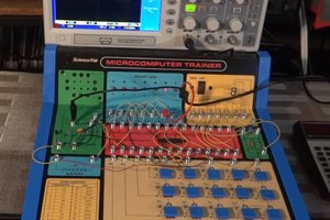
Congratulations on being a worthy winner. Nice job you did there. 👍

  Are you sure? yes | no

Michael Wessel wrote 09/07/2022 at 10:38 point

Thank you Ken, appreciate it!

  Are you sure? yes | no

Mike Szczys wrote 10/11/2021 at 18:35 point

Oooh, it's beautiful! I think the bubble display feels much cooler than the Nokia display. It's kind of a gimmick that grabs your attention right away and makes you want to sit down and play with the system. It's also quite snappy judging from the demo videos.

  Are you sure? yes | no

Michael Wessel wrote 10/11/2021 at 20:41 point

Thanks Mike, yes they are lovely... you can still get them (NOS I suppose?) from Jameco - 2.95 $ each :-) 

  Are you sure? yes | no

Michael Wessel wrote 10/08/2021 at 14:48 point

good to hear! seems they are just waiting for a project then :-) 

  Are you sure? yes | no

aldolo wrote 10/08/2021 at 14:46 point

nice . i've got just a couple of bubble display around for my personal implementatio

  Are you sure? yes | no

Similar Projects

Does this project spark your interest?

Become a member to follow this project and never miss any updates