 Michael Wessel
To wrap up my 2021/10 RetroChallenge contribution, I wanted to use the opportunity to demonstrate the real Microtronic to you, and how IT can play the drums!
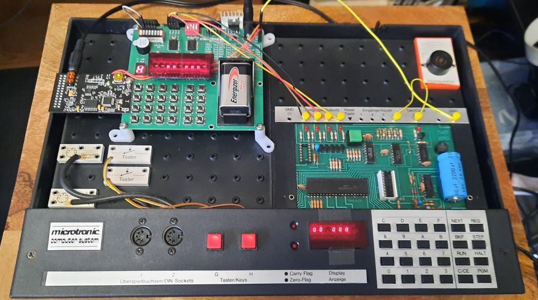
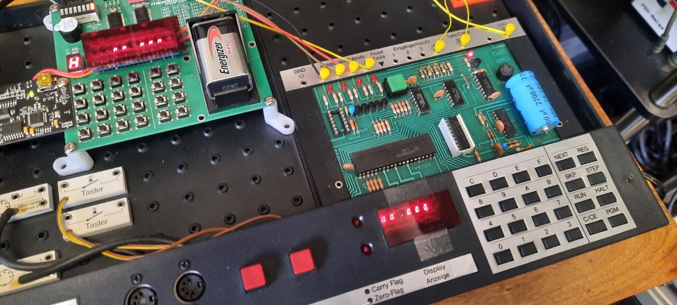
So this is the original from 1981 that I am emulating; note how the retro-authentic emulator (top left corner) is hooked up to it via 4bit GPIO connection:
Can it play the drums, too? Yes it can!
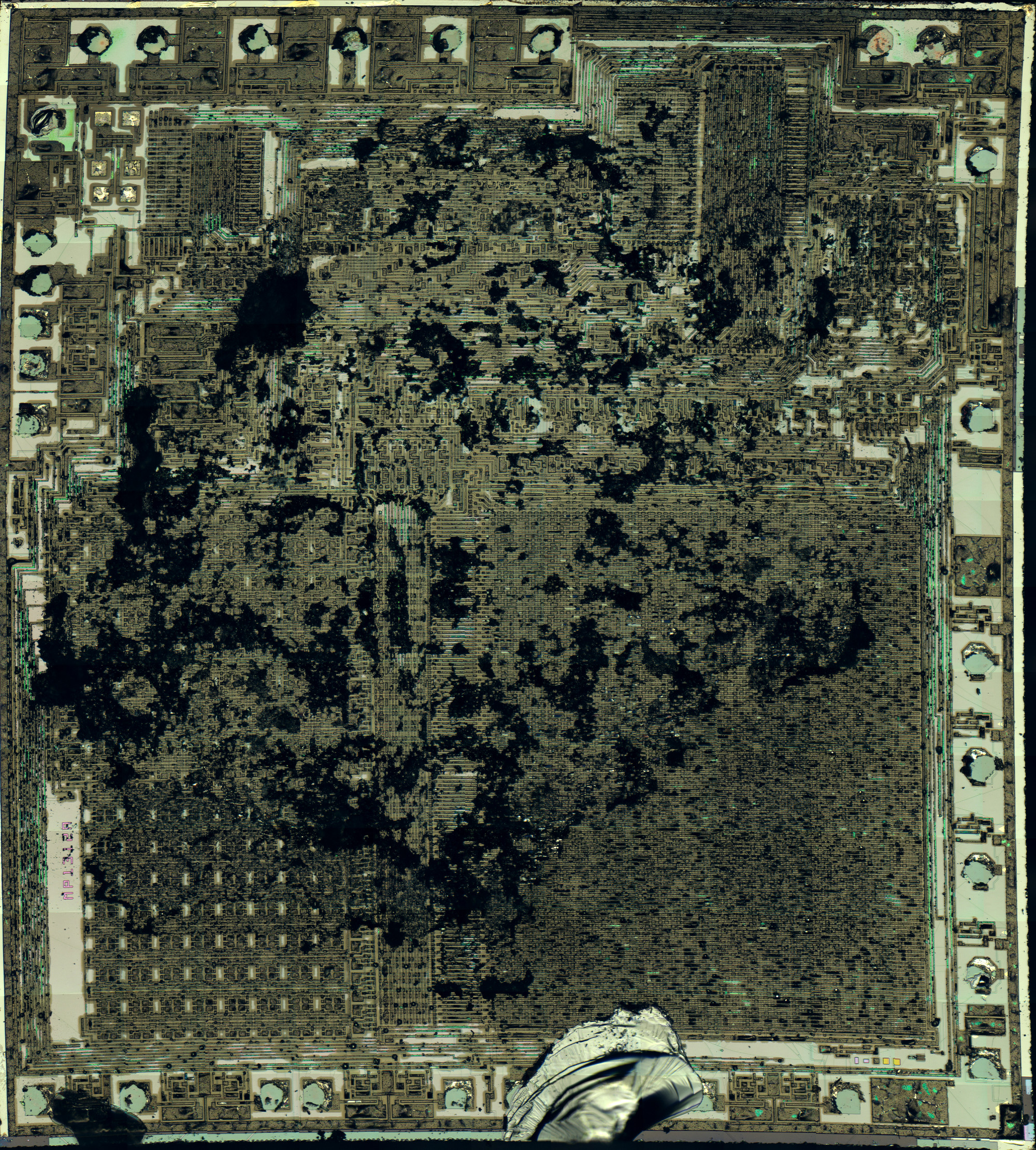
The original Microtronic uses a TMS-1600 masked-programmed microcontroller, clocked at 500 kHz. There is no EPROM or the like, hence making is impossible for me to hack the firmware / monitor to add "MIDI support" to the instruction set as I did for the emulator. The original TMS-1600 Microtronic firmware is not available, and what's worse, it is not straight-forward to read out the content of the mask-programmed microcontroller ROM!
I wish they had used an extra ROM or EPROM for the firmware / monitor program, but that would have driven up the price quite a bit. After all, the TMS-1600 is a microcontroller, not a CPU, and not requiring all the additional chips was and is a major selling point for microcontrollers. TI marketed the TMS-1000 series as "computers on a chip". The TMS-1000 series were the first microcontrollers available on the mass market. Flash memory probably didn't even exist back then, so Busch probably had to sent a tape containing the ROM mask to Texas Instrument in 1979 / 1980. I guess Texas Instrument "programmed" these chips directly in the factory (were other companies besides TI capable of doing this? not sure). At one point I also checked with TI support if they would have the mask files in the archives somewhere, but to no avail of course. I had no success with Busch either.
I was debating with myself the idea of sending a Microtronic TMS-1600 to Sean Riddle who decapped a number of TMS 1000-based MCUs and extracted the ROMs (!), e.g., from the SIMON game, as well as a number of TI calculators. But I haven't convinced myself yet that I want to sacrifice one of these ultra rare chips. Decapping is obviously a pretty destructive process, so I haven't reached out to Sean yet. AFAIK, Sean even has a TMS-1100 emulator. It would be awesome if one day the original Microtronic firmware was running on an emulator such as mine! After all, my Arduino emulator firmware was written be hand, by re-engineering the instruction set and the monitor program, with no knowledge of the original firmware program. Which of course also made extending it (as demonstrated here, for MIDI support and what have you) much easier. And I certainly prefer Arduino and C over TMS-1100 assembly... the TMS-1000 has a VERY interesting architecture, check it out. Things have changed quite a bit since these early days! Programming TMS-1000 assembly would be an interesting challenge in itself! Luckily, I didn't have to do that.
So, back to the drums. To make the original Microtronic play the drums, we cannot connect the X2 MIDI module directly to it. It is impossible for it to generate MIDI data with its limited resources (31250 BAUDs? are you KIDDING ME?) However, we CAN hook it up to the emulator using GPIO, which can then act as a drum module for it. Hence, I am simply using the Microtronic's GPIOs. The Microtronic is sending the 4bit drum number to its digital outputs, and 4 cables + 1 GND transmit that to the digital inputs of the emulator, which simply samples the port as fast as possible, in a loop, and whatever it reads it outputs to MIDI. As simple as that.
Now, that's of course only possible because we have the 0 drum which means "no sound". Note that there is no common clock signal between the two, so this is purely asynchronous communication, with all its problems. But it works!
On the Microtronic side, the transmit program is the following; it simply steps through all the drums from 0 to 15:
# display register 1
00 F10
# add 1 to register 0
01 510
# output register 0 to digital outputs
02 FE0
# move 0 into register 1
03 101
# output register 1 (= 0) to mute the drum
04 FE1
# a number of NOPs to slow down the program
05 F01
06 F01
07 F01
# goto / JP to 01, run in a loop
08 C01
In the video I am also showing how to adjust the speed by varying the number of NOP instructions between addresses 05 and 07. I turn this into an interactive "real time" drum computer by replacing 510 (= add 1 to register 0) with FF0 (keyboard input / KIN into register 0).
It would also be possible to use 16 Microtronic registers to input a 16step drum pattern, and play that back by sending out the corresponding register values one by one over the digital output port, step by step. But note that we only have blocking input available. So this would result in a program similar to the one in Update 3; we cannot change the drum pattern on the fly:
https://hackaday.io/project/180252/log/199020-retrochallenge-retrochallenge-update-3
On the emulator / receiver side, the sampling program is very simple as well:
# display register 4
00 F14
# enable MIDI output
01 022
# read digital inputs into register 4
02 FD4
# output drum number in register 4 to MIDI
03 044
# loop
04 C02
So, this wraps it up for me for this year's RetroChallenge!
Thanks for reading, watching, and I hope you enjoyed seeing the 1981 original Microtronic in action, and listening to it playing the drums!
Discussions
Become a Hackaday.io Member
Create an account to leave a comment. Already have an account? Log In.