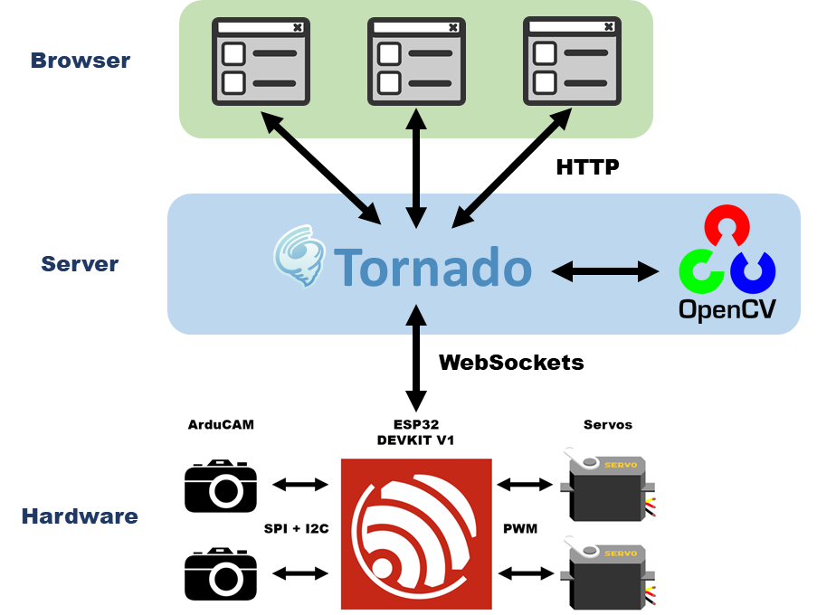
The PanoCama is a design for taking stereoscopic panoramic photos. By panning and tilting the cameras, the device can reconstruct a single wide-angle image through image stitching. Through its dual-camera design, the system can create rudimentary disparity maps as a precursor 3D environmental mapping. Image stitching and computer stereo vision are both computationally expensive tasks. Thus, to accelerate processing and prolong battery life, images are processed by a dedicated external server. While the server handles image processing, The onboard microcontroller, MCU, is responsible for interfacing with both cameras, controlling the pan-tilt servos, and maintaining web connection with the server. Rather than directly hosting a web server on the microprocessor, a separate device acts as proxy and issues commands to the device.
The main parts of this project fall into a few broad categories: ESP32 firmware, Tornado web server, panoramic stitching, camera calibration, stereo correspondence, PCB designs, and 3D printed parts. I made a working prototype with an ESP32 DEVKIT V1, a pan-tilt servo kit, and two SPI cameras. The main focus of this project is further exploring PCB design and image processing. Thus, the design uses a prebuilt pan-tilt system from Adafruit rather than custom 3D printed or machine pieces. Similarly, rather than multiplexing parallel buses from two OV2640 image sensors, the design uses prebuilt ArduCAMs- 2MP SPI camera modules. So far, I produced two PCBs: one closer to the breadboard prototype and another using the ESP32-WROOM-32 module that includes some additional previously unsupported features.
The image processing portion of the project uses the Python OpenCV library. The library supports both image-stitching and stereo correspondence but does not contain any state-of-the-art algorithms out of the box. For verification of some OpenCV results, I used the MATLAB image processing toolbox. While image stitching works well in test cases, generating stereo disparity maps proved more difficult. Thus, computer stereo vision and 3D environmental mapping are areas of future work.
Hardware Design
Overall, the hardware design is pretty simplistic. The Mini Pan-tilt system is from Adafruit and uses two servo motors with one controlling yaw and the other controlling pitch. While incapable of full 360-degree motion, the kit is sufficient during prototyping. The servos are controlled with pulse width modulation (PWM) from the microcontroller. Since the design is only concerned with panoramic pictures, the jerkiness of servo motion is irrelevant. If I work further on the project, building a more custom pan-tilt setup would be a good direction to investigate.
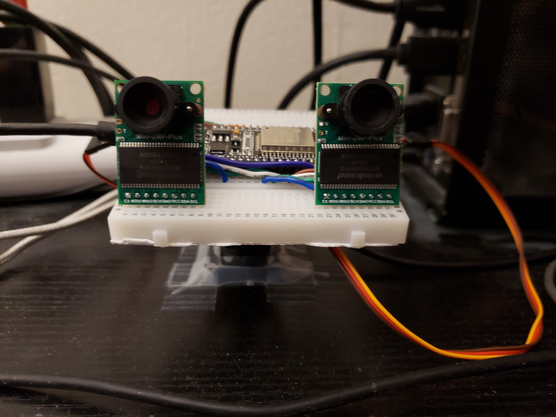
Electronics-wise, the design uses two ArduCAM SPI cameras and an ESP32 to handle processing and WiFi communications. The picture above shows a working prototype built on a breadboard that was used during testing. The camera modules greatly simplify things: they improve the frame rate with an internal frame buffer, and allows easy addition of more cameras. Implementing these additions would have been a substantial effort worthy of an additional project. The interface for the cameras is a little unusual, it seems that commands to the camera are issued over I2C while the image data is sent over SPI. What's more, since both cameras have the same I2C address, I had to initialize an additional I2C bus on the ESP32.
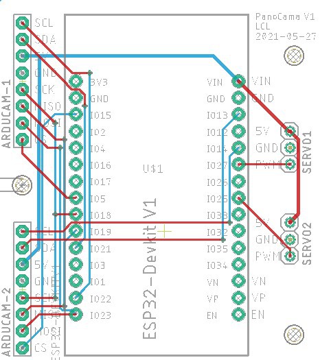
From this design, I created a pretty simple breakout board for the ESP32 and the other parts. Originally, I had issues interfacing with the cameras on the breadboard due to SI issues from the jumpers. The SI issues were solved when I replace the jumper with wire cut to the proper lengths. So, this PCB is mostly intended to fix any lingering SI issues and to stop any wobble of the cameras that might comprise the calibration of the cameras. Like before, the ESP32 is powered via USB 5V. All the components- the cameras and the servos- are 5V tolerant.
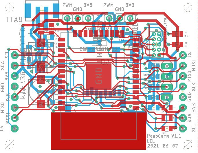
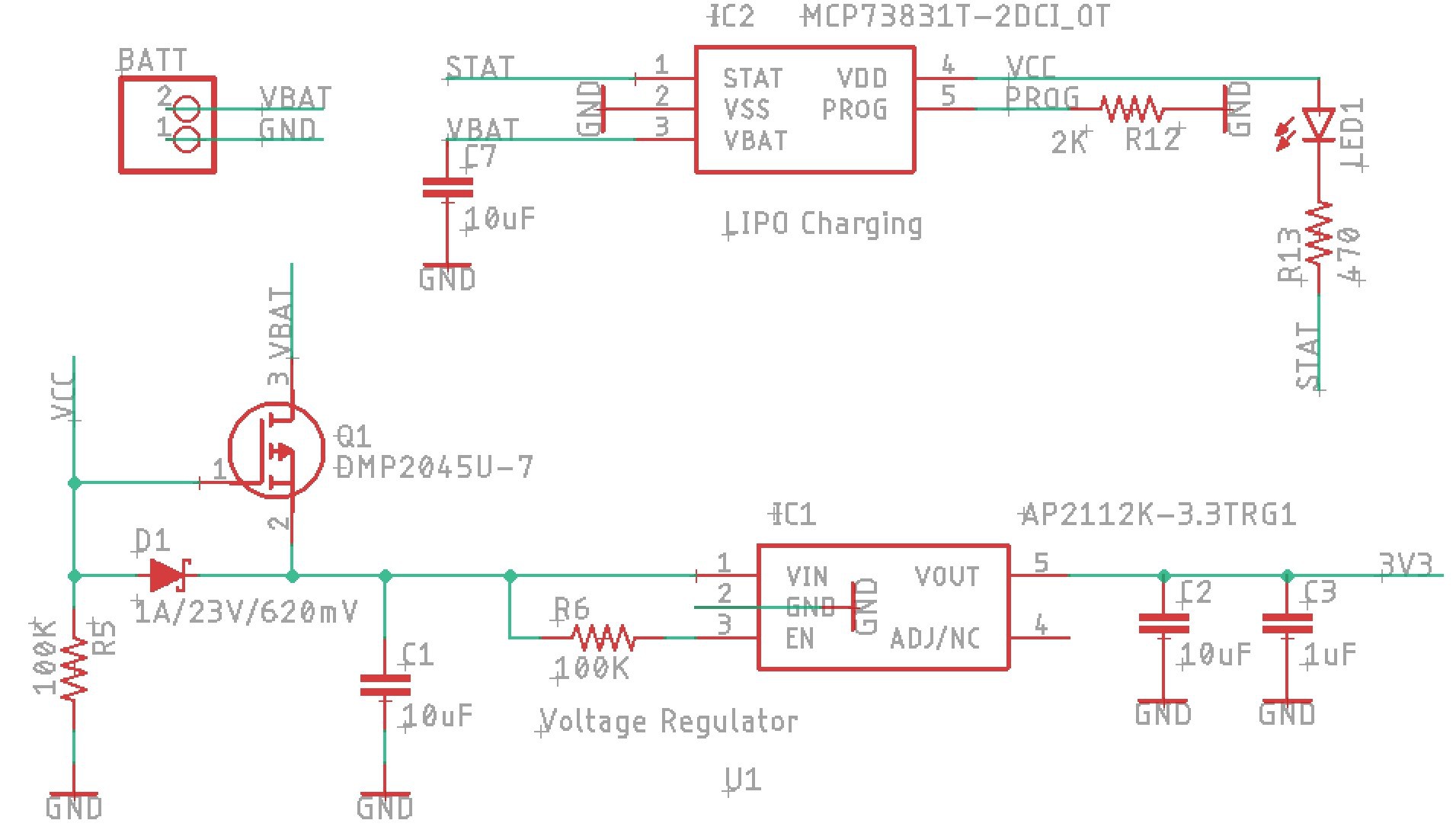
This is a second iteration of the design that breaks out an ESP32-WROOM32 (what a mouthful). With this design, I also added some additional features: While I had some issues getting JTAG debugging to work with the DEVKIT V1, I suspect that the issue is that the boot strapping pins are not set correctly during boot. So, I added some pull-up and pull-down resistors to the design. I also included an SD card reader over SPI and a battery charging setup. SD cards run at 1.8 V. Ideally, you would use a level shifter from the 3.3V logic of the ESP32 module. However, since the JTAG debugging pins take up some of the high-speed SD I/O pins, I opted to use the slower SPI method instead. At this point, I don't think the attenuation from using resistors is that significant, so I used them instead of a dedicated 3.3V to 1.8V level shifter. Lastly, with the battery charger and parts of the voltage regulator, I mostly replicated the design on the open-source Adafruit HUZZAH32 - ESP32 Feather. I have attached the EAGLE files for both designs in this project. Please note that I have not had time to fully test either design, so no guarantees.
3D Printed Part
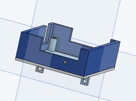
For further testing, I created a custom 3D printed piece for mounting the second revision PCB to the Pan and tilt base. This likely requires some modification before actually 3D printing it due to its unusual geometry. It is designed to work with an SG90-microservo, the same motor used in the pan-tilt kit.
Software Design
The code developed for this project can be separated into three parts: ESP32 firmware, WebSockets/website, and image processing.
Firmware
Firmware primarily interfaces with the cameras and servos onboard the device. Furthermore, the firmware handles requests received downstream over WebSockets and upload images upstream. To speed up development, I used the Arduino environment, but with PlatformIO instead to take advantage of VS Code. Originally, I tried setting up JTAG debugging with the ESP32 (which is supported in theory). While the J-Link EDU MINI seems to be recognizing the ESP32 it seems to have trouble actually writing to it. Ultimately, I gave up and just programmed over USB.
Overall, thanks to prebuilt Arduino libraries the firmware development wasn't too bad. PWM for the servos is natively supported. WebSockets on ESP32 is a little trickier but made much easier with the Arduino WebSockets library. This library was chosen due to its support of WebSocket clients- since my computer is acting as the server. Requests to the ESP32 are stored and parsed as a static JSON document. Note that the embedded JSON library is very interesting and allows you to allocate a fixed amount of memory for storage.
Interfacing with the cameras was surprisingly involved. Since I had two active cameras that required two separate I2C buses, I had to change go into the ArduCAM provided library and add a class variable for the I2C bus. Otherwise, it always defaults to the first I2C pins. To start image transfer, the ESP32 first has to read the buffer size over I2C then transfer the data within the buffer over SPI. Overall, this process is pretty similar to the original interface of the OV2640 camera- the one used within the ArduCAM. Note at this point, the image data is in JPEG format with 0s after the end of the image. So further processing is needed to get the start and the end of the image data.
Webserver
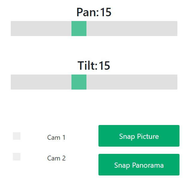
A Python Tornado server handles the bidirectional communication between itself and the ESP32 device via WebSockets. While using Tornado is fine for the prototype, if I move on to the cloud, I probably want a proxy server such as NGINX for load balancing and handling malformed requests. User controls are formatted and sent from the webserver to the ESP32. From the website, users can manually pan/tilt the device and capture images. Currently, the Tornado server acts as an intermediary with two active WebSockets connections. One socket monitors the website and relays relevant requests to the ESP32. The other socket sends JSON requests to the ESP32 and receives binary image data back.
Image Processing
While not fully integrated into the website, this project developed several types of post-processing code through OpenCV. This includes image stitching, stereo calibration, and disparity map generation.
Image Stitching
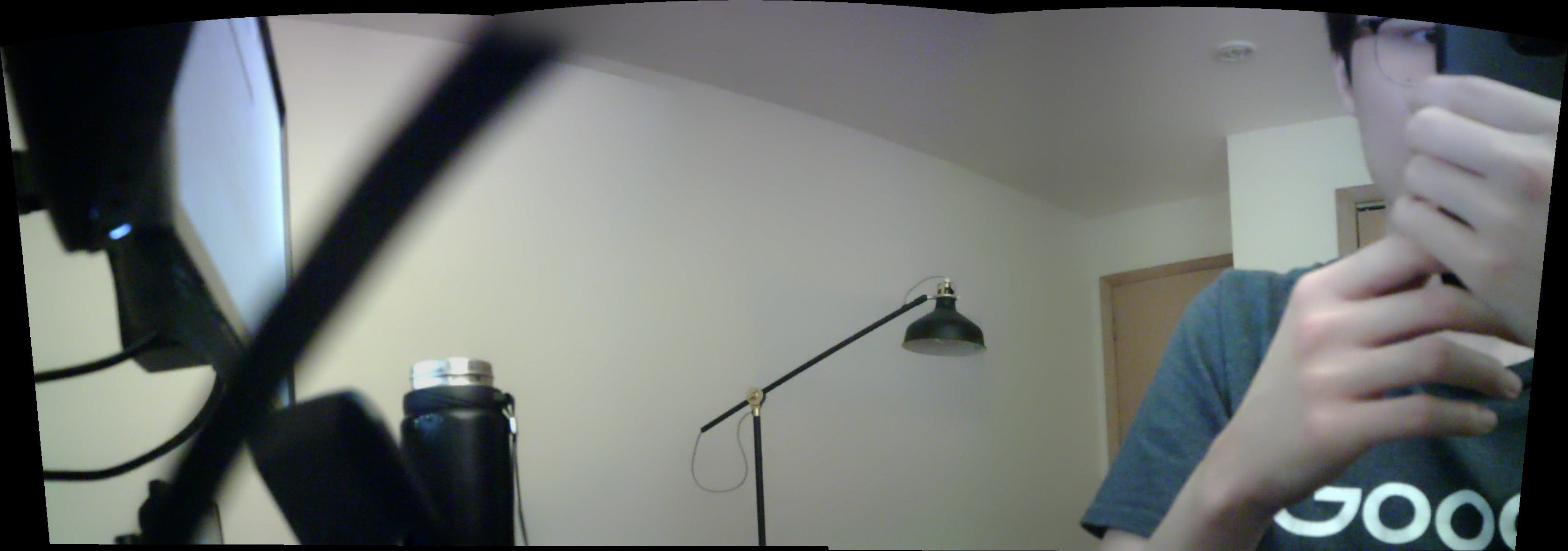
Image stitching combines an arbitrary number of images together into a panoramic image. The general approach is based on keypoint matching, so the system will struggle with low-quality images and images without significant feature overlap. OpenCV contains a very good stitcher out of the box and is able to make panoramas pretty effectively. Not only does it work for an unordered set of images, it automatically undistort and blends the boundaries.
With OpenCV, you can also dive into low-level functions and perform your own image stitching. The general procedure is as follows...
- Detect keypoints on each image (SIFT used in my implementation)
- Get descriptors for each keypoint between the two images
- Match descriptors positions between Images
- Calculated the transformation to match features- Homography matrix
- Wrap image according to calculated homography matrix
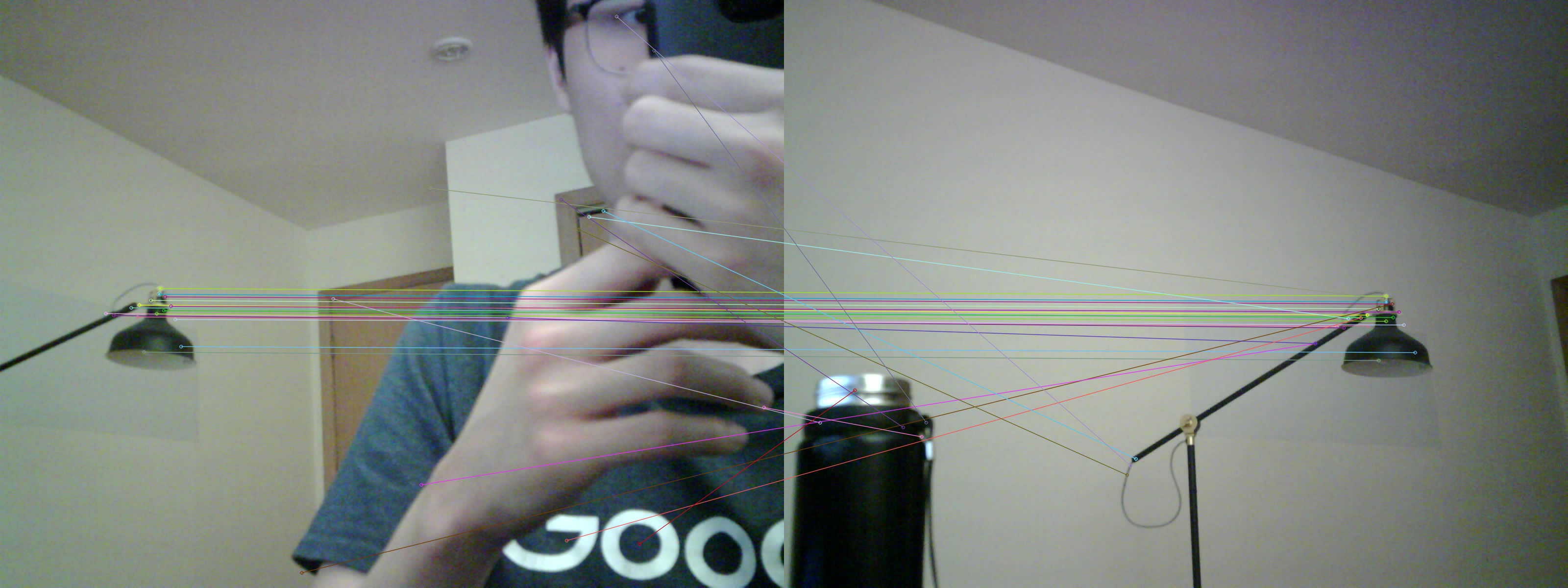
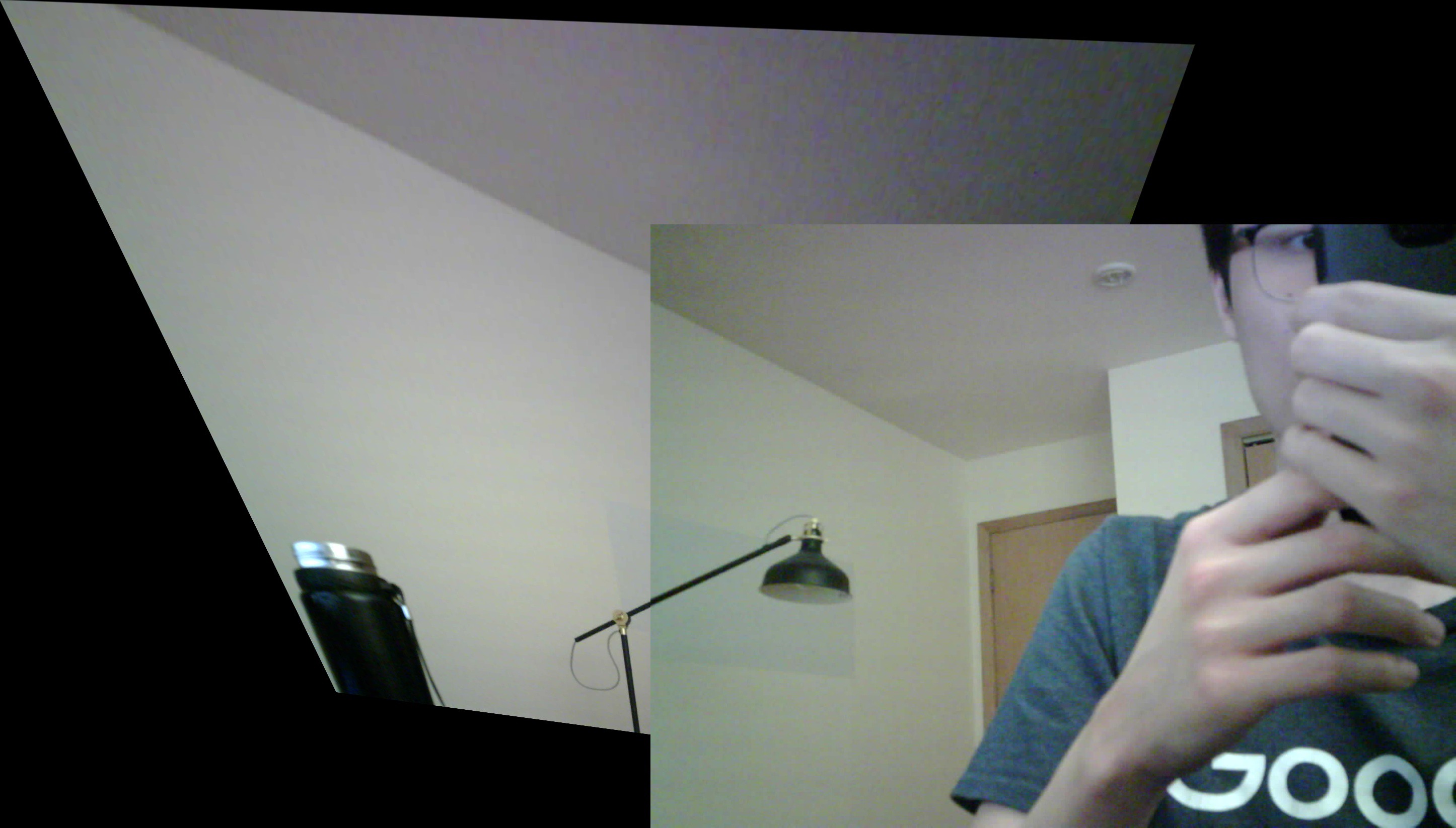
As you can see this simplistic algorithm is not always perfect, especially with plain backgrounds. There are further optimizations that can be done.
Stereo Calibration
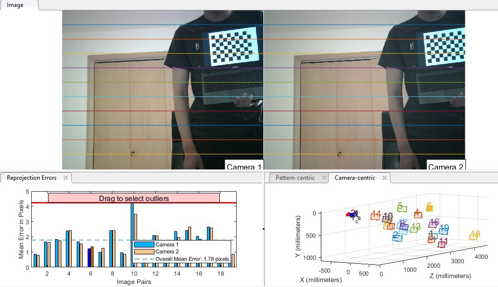
Stereo calibration is the process of aligning images from two different cameras and an essential step for calculating image disparity. Not only does this process undistort individual images, but it also horizontally aligns the features on both images; the alignment assists in pattern matching during disparity map calculations. One way to do this mapping is if your picture has many key points. In this case, you don't need to calibrate as each keypoint is matched and rectified instead. Otherwise, you need to take many pictures from both cameras with a known pattern. This process is fairly interesting: you have to hold a checkerboard pattern at various positions. I would recommend using the OpenCV provided pattern on a laptop. In theory, any arbitrary checkerboard is fine; however, I find that the algorithm has trouble picking out dense checkerboards. The recommendation is around 10-20 sets of images. For my cameras, I need around 20 for good-looking alignment.
Something I found helpful for this process is the stereo calibrator app from MATLAB. It generates a visualization of both the final rectified image and the approximated positions of the cameras. This is an incredibly good troubleshooting tool and saved me a lot of head-scratching.
Disparity Maps and Stereo Correspondence
Disparity map algorithms usually search nearby for a group of matching pixels on the other image. By calculating this offset at different positions on the image, a disparity map is generated. From here, just like we do subconsciously, an algorithm can calculate the depth from the image given a disparity map. In the simplest algorithms, the matched block is assumed to be purely horizontally shifted; thus, a good stereo calibration is very important. For this project, I looked at two methods: block-matching (BM) and semi-global block matching (SGBM). Semi-global block matching is said to be better since it searches multiple directions for the matching block. Predictably, it is also slower. With both block matching algorithms, there are many parameters to adjust: uniqueness ratio, filters, disparity search range, etc. Despite trying many different combinations of settings, thus far, I am unable to get a good result. Ideally, you would want a smooth, continuous disparity map. However, for both the BM and SGBM methods, I get very noisy images with large black regions in the middle of the shape.


There are more advanced techniques I could attempt. For example, there is post-processing to clean up noisy disparity maps or even neural network-based approaches that are commonly used in autonomous vehicles. But, this is where I leave the project for now.
Closing Thoughts
I definitely learned a lot about image processing through the course of this project. There are many good directions that I could take from here. This report turned out much longer than I imagined, so thank you for reading!