Eugene Choe
Hardware Details
The Radiator Knob Controller
A major aspect of my device is being able to physically turn the radiator knob clockwise and counterclockwise in order to turn the radiator on or off. This mechanism is driven by a stepper motor attached to a 3D print that fits onto and tightens around my radiator knob. The stepper motor is powered by a motor drive controller that is connected to a 24V DC wall power supply. All of this is controlled by an ESP32-CAM module, which was very cost-effective because it was an extra ESP32 module that came with the kit provided with the class and added no immediate cost to my project. This is programmed using an FTDI programmer.
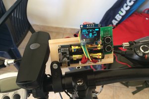
As seen on the left side of the image below, I use an arm with clamps on both ends to hold the motor in place while turning the radiator knob. I wasn't able to get a picture of my device on my actual radiator in my apartment as I am currently back home, but I was able to get the general set up on my table. Some differences are that the C clamp currently fastened to the table would instead be attached to the valve between the radiator knob and the radiator. The two limit switches attached to this clamp would also need to be adjusted as the radiator knob is higher off the ground than the radiator valve.
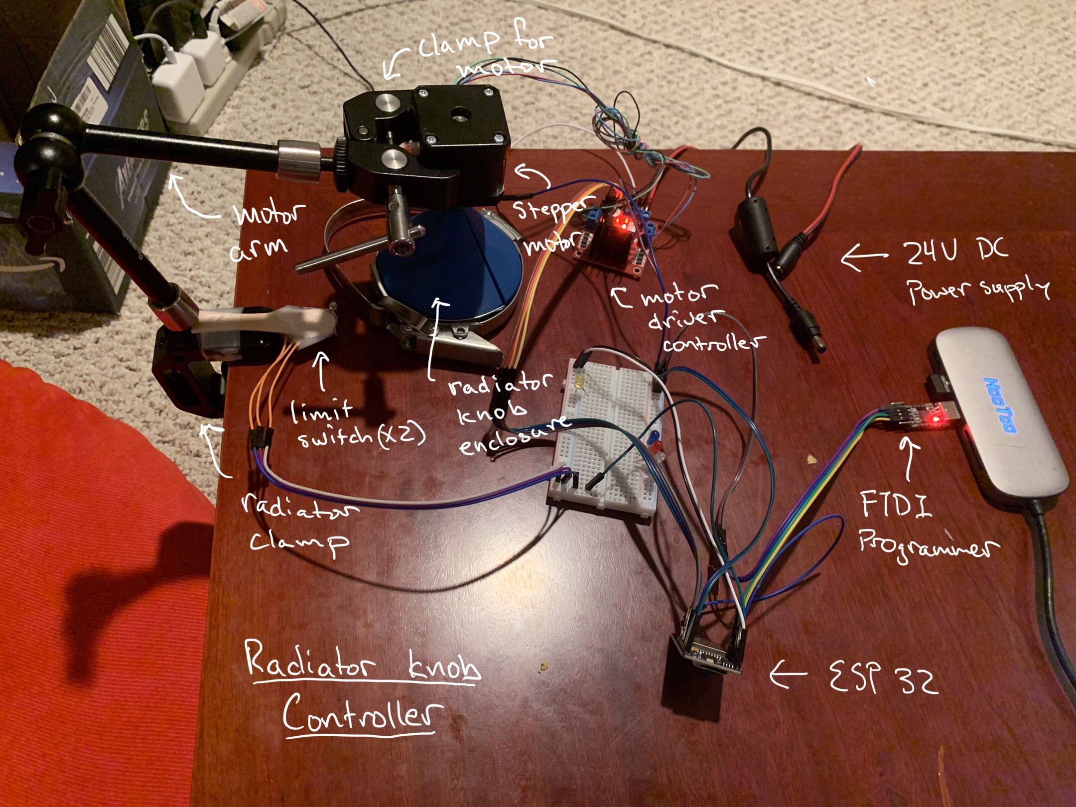
In my original design, I was planning on adding gearing in between the motor and the 3D print in order to increase the torque as the radiator knob can be very sticky and hard to turn. However, I realized that I could eliminate this step by increasing the power supply to 24V from the original 9V I was testing my prototype with, which allowed the stepper motor to output much more torque. This freed up time to add features like a physical thermostat into my project.
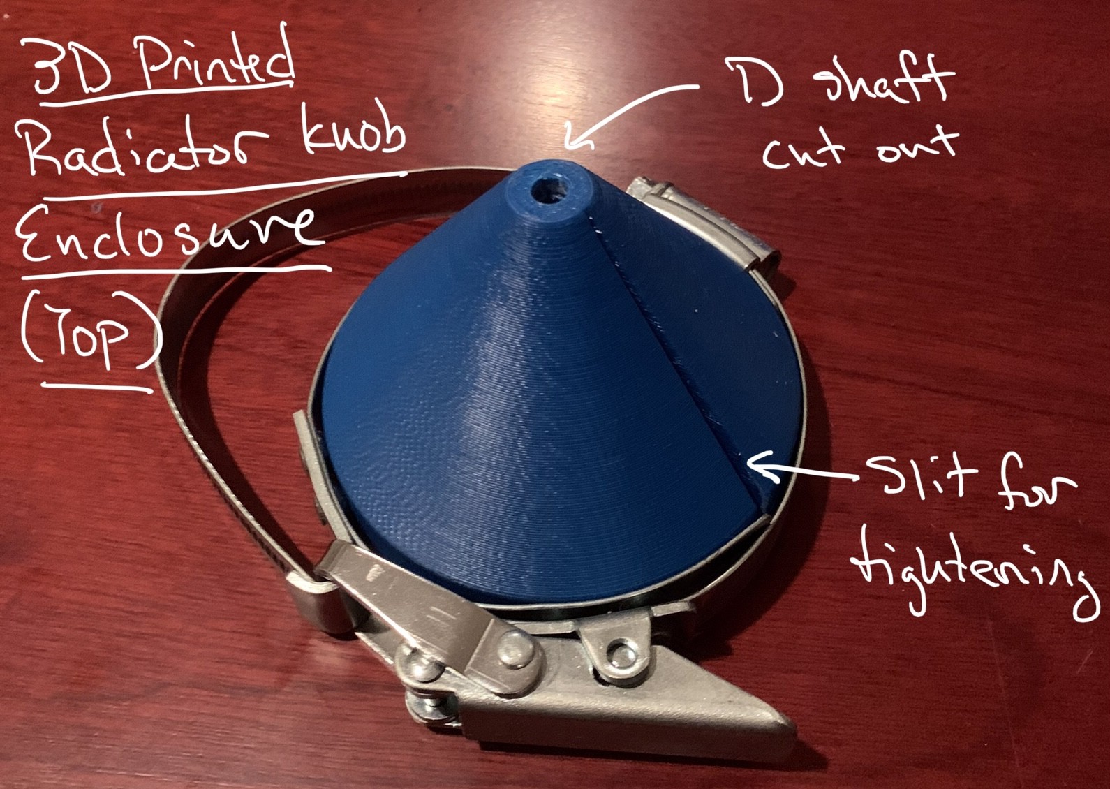
Radiator Knob Enclosure
This 3D print fits onto and tightens around my radiator knob. It has a special D shaft cut out that is a perfect fit for the stepper motor. The 3D print also has a slit going through the entire model that allows the print to be loosely put onto the knob and tightened to hold onto the knob.
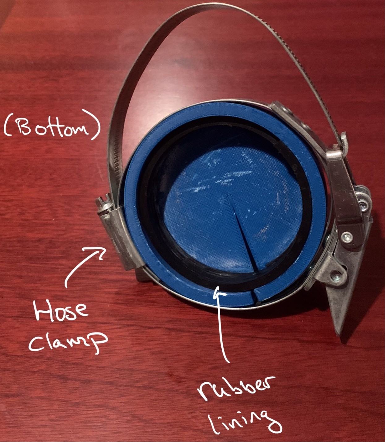
The bottom of the 3D print shows the cutout for the radiator knob to fit into and also the hose clamp that allows the print to tighten. There is also a rubber lining on the inside of the cutout to allow maximum friction between the print and the radiator knob.
Thermostat/Webserver
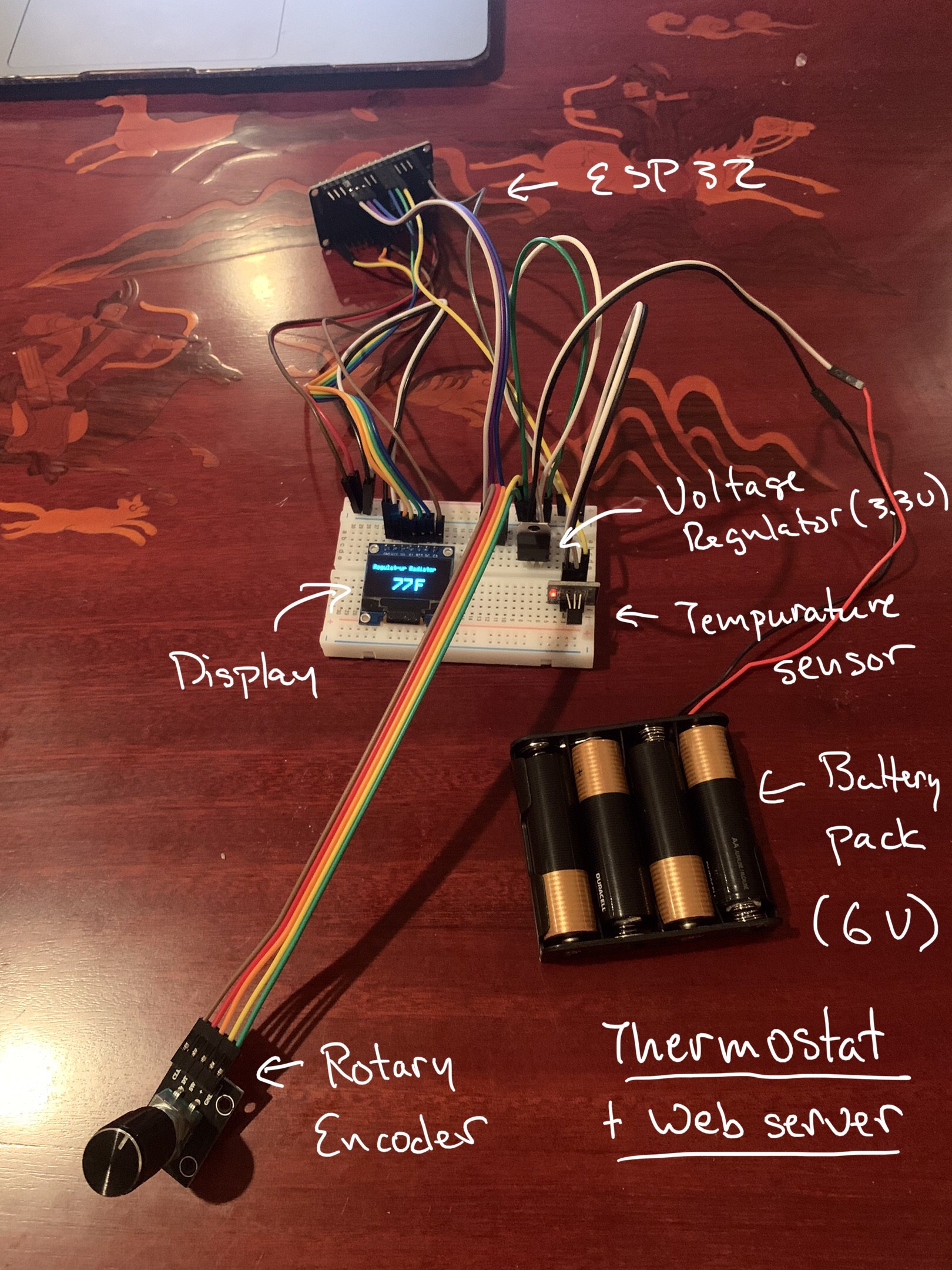
Another aspect of my project was creating a physical thermostat that can be placed anywhere in the room. At the heart of this is a DOIT ESP32 devkit that controls all the peripherals while also acting as the webserver. Some of these peripherals include an OLED display, temperature sensor, and rotary encoder. The OLED display communicated through SPI and so needed 5 pins for MOSI, CLK, DC, CS, and reset. The temperature sensor only needed one GPIO pin as it relayed the data digitally. The rotary encoder needed three pins. The whole device is powered by a battery pack that holds 4 AA batteries (6V), which is reduced to 3.3V by the voltage regulator.
Software Details
On the software side, I decided to use the Arduino IDE as it was relatively simple to use and provided many ready-to-use libraries and example code.
Webserver/Website
As mentioned before, the webserver was hosted on the DOIT ESP32 devkit driving the thermostat. I was able to set up the webserver by using the ESPAsyncWebServer library and connected to the WiFi using the WiFi libraries. I then used SPIFFS to upload the HTML, CSS, and JavaScript files for my website onto the ESP32 module and was able to serve them for each HTTP_GET request through using ESPAsyncWebServer.
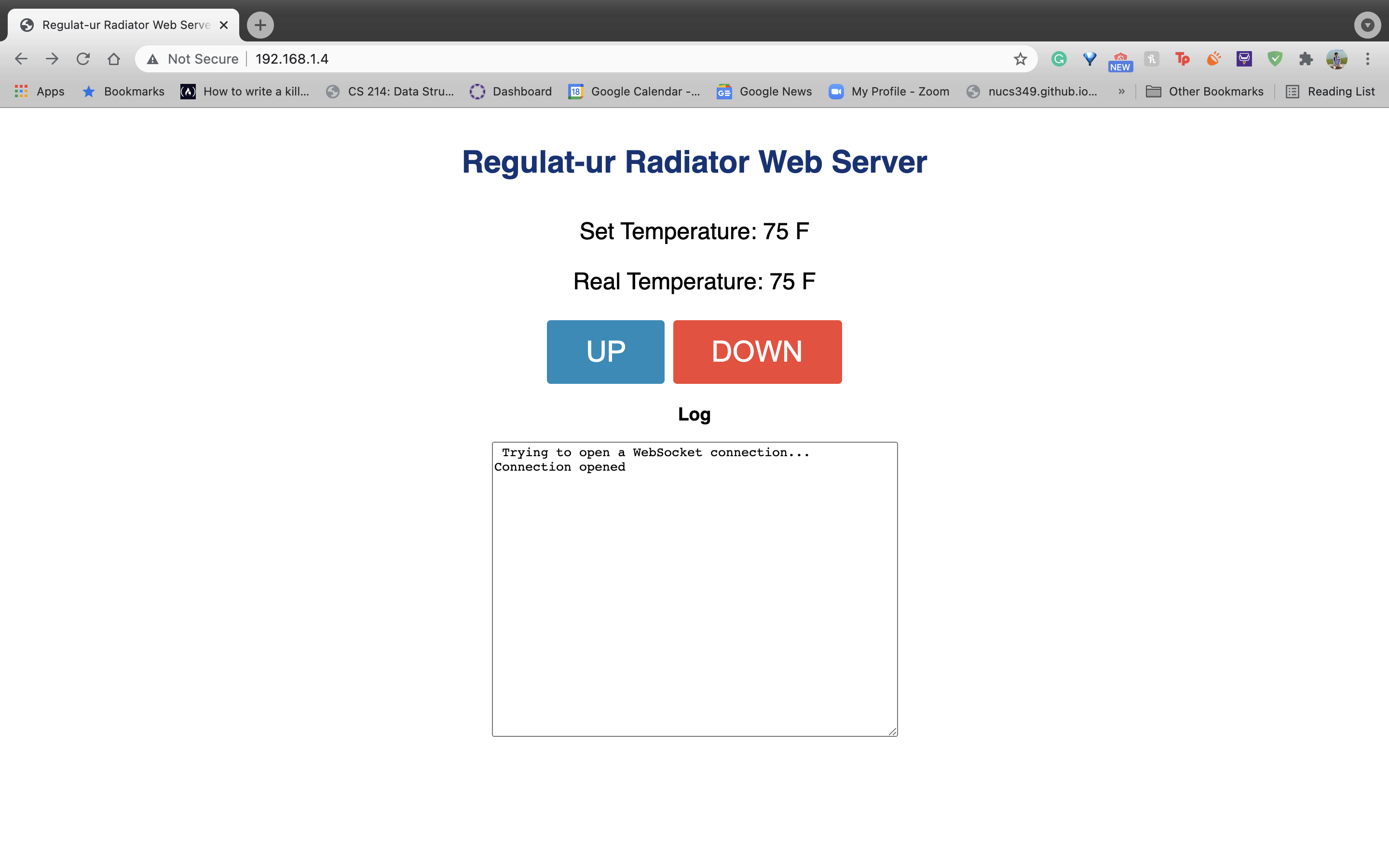
I was also able to get devices communicating with each other through the webserver using WebSockets. This was also implemented using ESPAsyncWebServer. I used the ArduinoJson library to send data as a JSON file between the website and the webserver. This library allows the serialization and deserialization...
Read more »
 Hulk
Hulk
 bosko
bosko