 Matthias Kampa
Why?
I was curious to experience how it looks and find out if it works. It might also be a slightly more engaging alternative/addition to showcasing the uncertainty principle with two razor blades and a laser.
How did it turn out?
Better than expected. The display is easy to read and just floats in midair. The darker it is, the better it works, but as you can see in the video it is also visible in a brightly lit room.
Mechanics
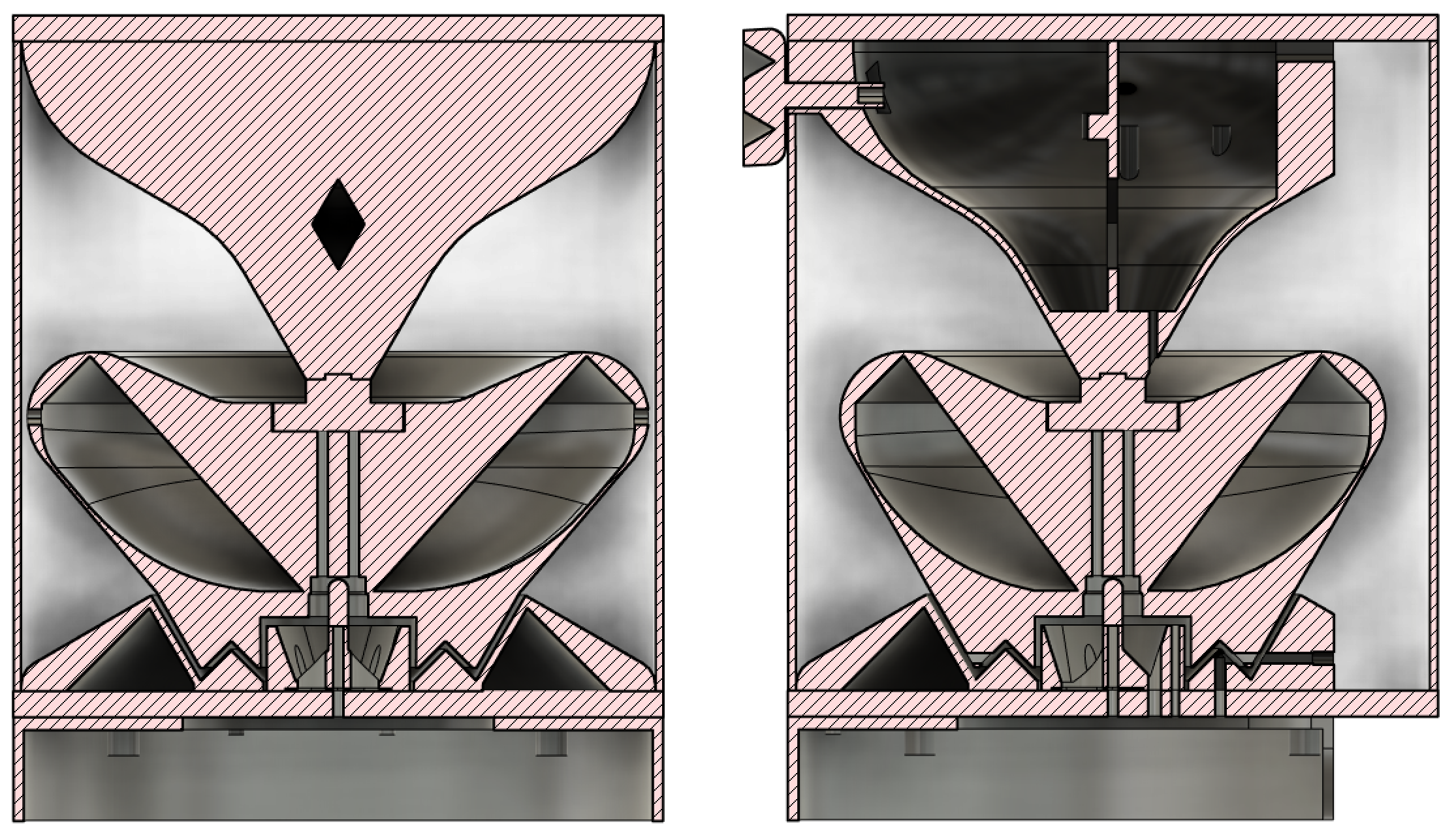
The device is divided into two units: The top consists of the brushless motor+driver and the rotating reflector, the bottom contains the LEDs and their control. Because of the modularity the multispectral LED module can be used for other experiments or as fancy lighting. Since I wasn't sure if the concept is feasible I planned to repurpose it by printing a diffuser and turning it into an overengineered lamp.
An acrylic tube provides a rigid yet "invisible" connection between the units and some safety for/against the reflector. It sits on three red silicone foil pieces on each end for additional noise/vibration reduction. The reflector has a ball bearing that provides alignment and stability. It slides on a brass pin in the base. The space between LED-unit and reflector is shaped to prevent light bleed. The reflector has two slits to synchronize the light pulses via a light barrier. Because the reflector has two holes it display two updates per rotation, effectively halving the required rotational speed.
Most parts are 3D-printed and optimized to reduce supports to a minimum. I used some cheap black PETG and white "Kexcelled K5-shade: light shield" PETG with a very high content of pigment. The pigment content reflects the light very well, but be aware that it prints worse than vanilla PETG, has worse mechanical properties and also stains the build-plate. I had to print a "cleaning-layer" to get it out of the textured build plate of our MK3S because it stained the following prints. A standard nozzle might also clog, but I printed everything with 0.6mm diameter and had no issues. At first I was a bit disappointed with the print quality, but the texture and artifacts on the overhang turned out to look pretty interesting and somewhat aligned with the weird design. In case you were wondering: Yes, the reflector is oval and not circular. That looks way cooler, still has low drag and most importantly fits on a 250x210 build plate while maximizing the display size.
Electronics
A raspberry gets the time/content via wifi and encodes 2D images into bytes that are sent to an ATmega via serial. Every byte represents one column. I want to add a yellow LED at some point to increase the height to 8 pixels. The width is set to 42, but can be altered easily. The mega's integrated operational amplifier is connected to the IR receiver to sync up the timer when the reflectors slit passes the detector. It pushes the pixel columns to LED drivers that are set to 700mA. The bottom base plate is aluminum and serves as a heatsink for the LEDs. The top is steel because it was cheaper and heavier (=more vibration dampening).
The BLDC motor is driven by a generic controller board. Since the setup is sensor-less it struggles a bit with the high rotational inertia of the reflector. But the pretty septagonal speed knob with exposed gyroid infill almost makes you forget about it.
Glasses
The diffraction grating glasses are 3D-cinema glasses that were refitted with 13.5k lines/mm dual axis diffraction grating foil (sounds way more expensive than it is). The fewer lines a filter has, the more the image will get stretched and the closer you will have to get to the device. Both sides have to be aligned perfectly parallel to create a proper stereoscopic experience. It would be even better to print glasses that hold one continuous piece of foil instead. For the videos I just held some foil in front of the camera.
Want to DIY?
Here are some more considerations if you would like to make something similar:
- Use an external power supply or cover mains & ground exposed metal.
- Use a different BLDC controller in case you would like to improve the spin-up. Make sure to limit the speed. The acrylic tube should contain a disintegrating reflector and the double holed design keeps the required rotational speed low, but let's not test it.
- Add a yellow LED, use different boards. Yellow wasn't available and the boards were extremely overpriced. Modifying the design for different LEDs should be straight-forward. I ordered a set of Luxeon Rebel LEDs on 3 aluminum star boards from luxeonstar.com for a total of ~65$ + shipping. I bet you can do way better... I'd recommend my usual go-to Osram Oslon SLL + 1 turquoise Rebel or similar.
- Because of the dual exit reflector the content has to be symmetric (back and front are the same). Closing one of the holes and one sync-slit would allow you to change that. Just alter the code to account for the increase in display width.
- My assembler is a bit rusty since I mostly code Julia now and the Python code is one of the first raspberry projects of my wife - tell us what we could have done better
- Let me know if you need some more info or help
Some other approaches:
- A conventional spinning LED PoV setup
- Lasers for ultra sharp lines
- Using a white light source + diffraction grating or prism + LCD or DLP for ultra high resolution
- Instead of translating 1D to 2D you can also translate 2D to 3D. Only tested with RGB, but amazing.