Introduction
For this project I sought to understand, at a low level, how a drone flies. To do this I designed and implemented the flight control software onto an ESP32 module using a 6-axis IMU.
The IMU sends its raw accelerometer and gyroscope data to the ESP over an I2C bus. The ESP then filters the noisy accelerometer and takes the integral of the gyroscope data. After this, roll and pitch are calculated from the filtered accelerometer data. The moving average is then calculated for roll and pitch data from the accelerometer. Finally, the roll and pitch data from both the accelerometer and gyroscope are fused to get the final readings and to further filter the noisy accelerometer data.
After this, the RPY data is run through a PID controller. These control values are then added to the motor command values based on the location of the motor around the IMU. These modified command speeds are then sent to the ESCs.
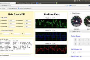
Finally, the user can, in a limited capacity send commands to the drone via WebSockets. The ESP hosts the WebSockets server through a soft access point that any tablet, phone or computer can connect to. This website displays the motor state (enabled/disabled) and the motor speeds when new commands are sent to it.
Hardware
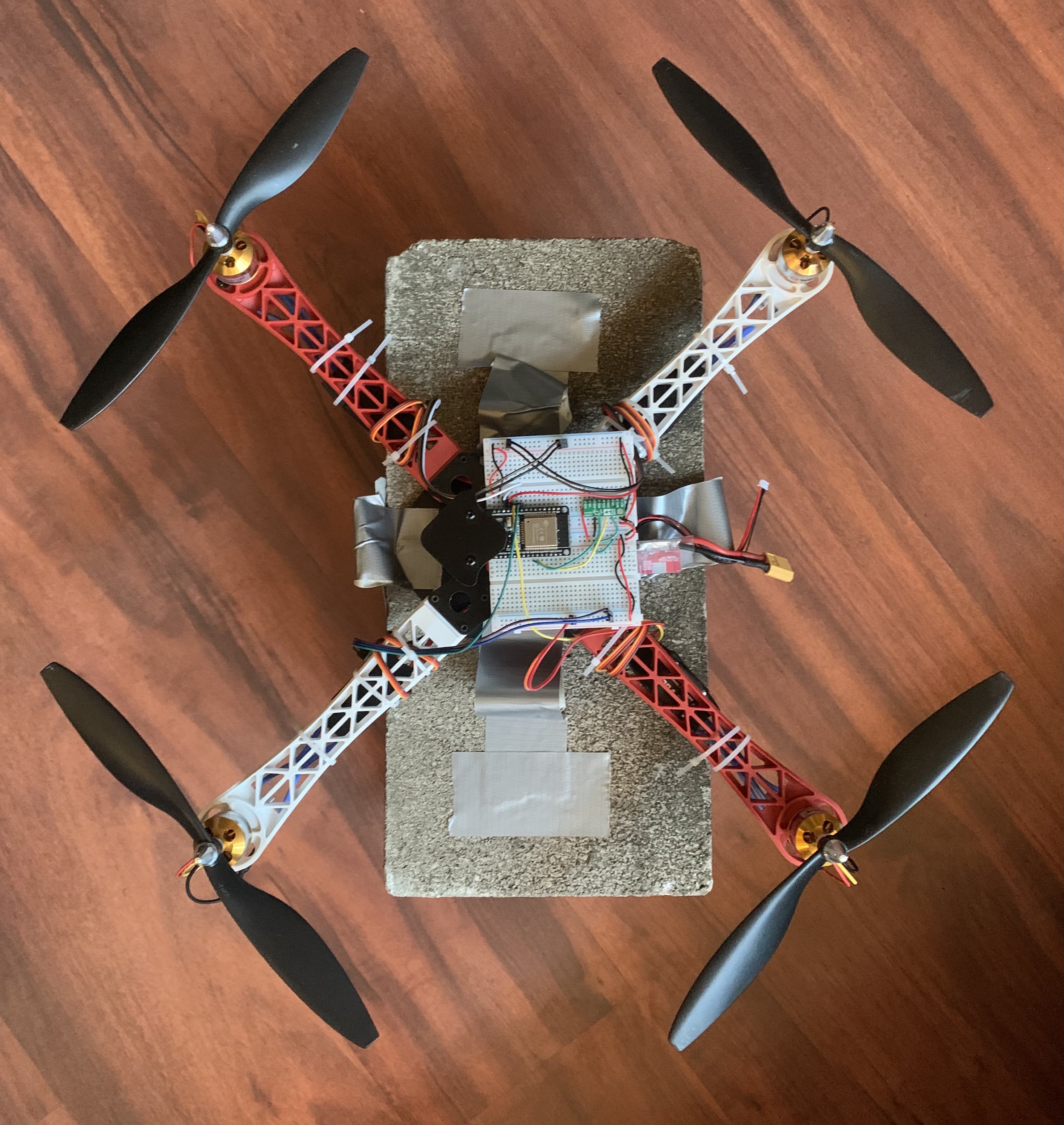
The mechanical and hardware components used to assemble this drone can be seen in the BOM.
Drone Kit
A drone kit was purchased instead of designed in order to increase the time that could be spent designing the flight control software. The components for this can be seen in the BOM.
IMU
The IMU is a 6-axis LSM6DS33 that is connected to the microcontroller via an I2C bus.
Microcontroller
The ESP32 handles all of the computation for the flight control software. It is powered via a voltage regulator provided with the kit (11.1V to 5V). The ESP is connect to the four ESCs via analog outputs and to the IMU via an I2C bus.
Software
The software for this drone is in two locations. The first is an IMU/I2C library programmed in C++ with Visual Studio Code. These libraries were created with the help of Adafruit's LSM libraries. The second location is in the main Arduino folder. This folder contains the main .ino file as well as the html, css, and javascript files for the website. The .ino file contains the program for initializing the SoftAP for the ESP, creating the WebSockets server, reading the IMU data, and performing the flight control.
Website Structure
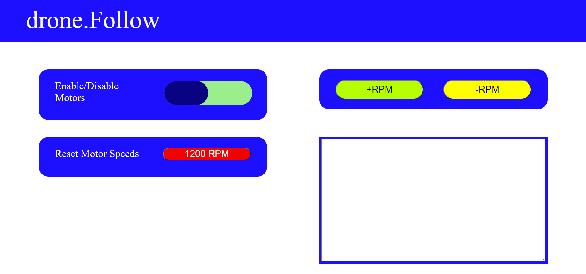
A very simple web interface was developed for sending commands to the drone. There is a switch for enabling/disabling the motors, a button to set the motors speeds to the lowest speeds that the motors can run at, and buttons for increasing the motor speeds of all of the motors (this functions as manually controlling the desired height of the drone). Finally, there is a log the displays data and comments on any button presses.
Sensor Filtering and Fusion
// read IMU data
read_accelerometer((accel),(accel+1),(accel+2));
read_gyroscope((gyro),(gyro+1),(gyro+2));

// low pass filter on accelerometer readings
Ax = (float) Ax + 0.05*(accel[0] - Ax);
Ay = (float) Ay + 0.05*(accel[1] - Ay);
Az = (float) Az + 0.05*(accel[2] - Az);

// calculate roll + pitch from accelerometer data
pitch_accel = 180 * atan2(Ax,sqrt(Ay * Ay + Az * Az))/M_PI;
roll_accel = 180 * atan2(Ay,sqrt(Ax * Ax + Az * Az))/M_PI;

// integrating gyro values to git roll pitch and yaw

roll = (float) gyro[0]*0.0174533 * dT;
pitch = (float) gyro[1]*0.0174533  * dT;
yaw = (float) gyro[2]*0.0174533  * dT;

// sensor fusion , thrust_const = 0.1
pitch = (1-thrust_const)*pitch + thrust_const*pitch_accel;
roll = (1-thrust_const)*roll + thrust_const*roll_accel;

// moving average calculations, MOVING_AVERAGE_SIZE = 15
sum_roll = sum_roll - readings_roll[ind];
sum_pitch = sum_pitch - readings_pitch[ind];

readings_pitch[ind] = pitch;
readings_roll[ind] = roll;

sum_roll = sum_roll + roll;
sum_pitch = sum_pitch + pitch;

ind += 1;
ind = ind % MOVING_AVERAGE_SIZE;...
Read more »
 Chris
Chris
 Jaspreet Singh
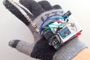
 RaptorTech