Close
0%
0%

PewPew OLED

They just keep on coming!

Similar projects worth following

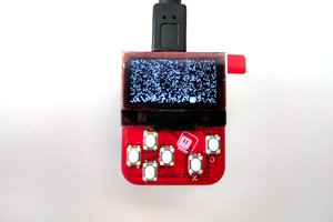
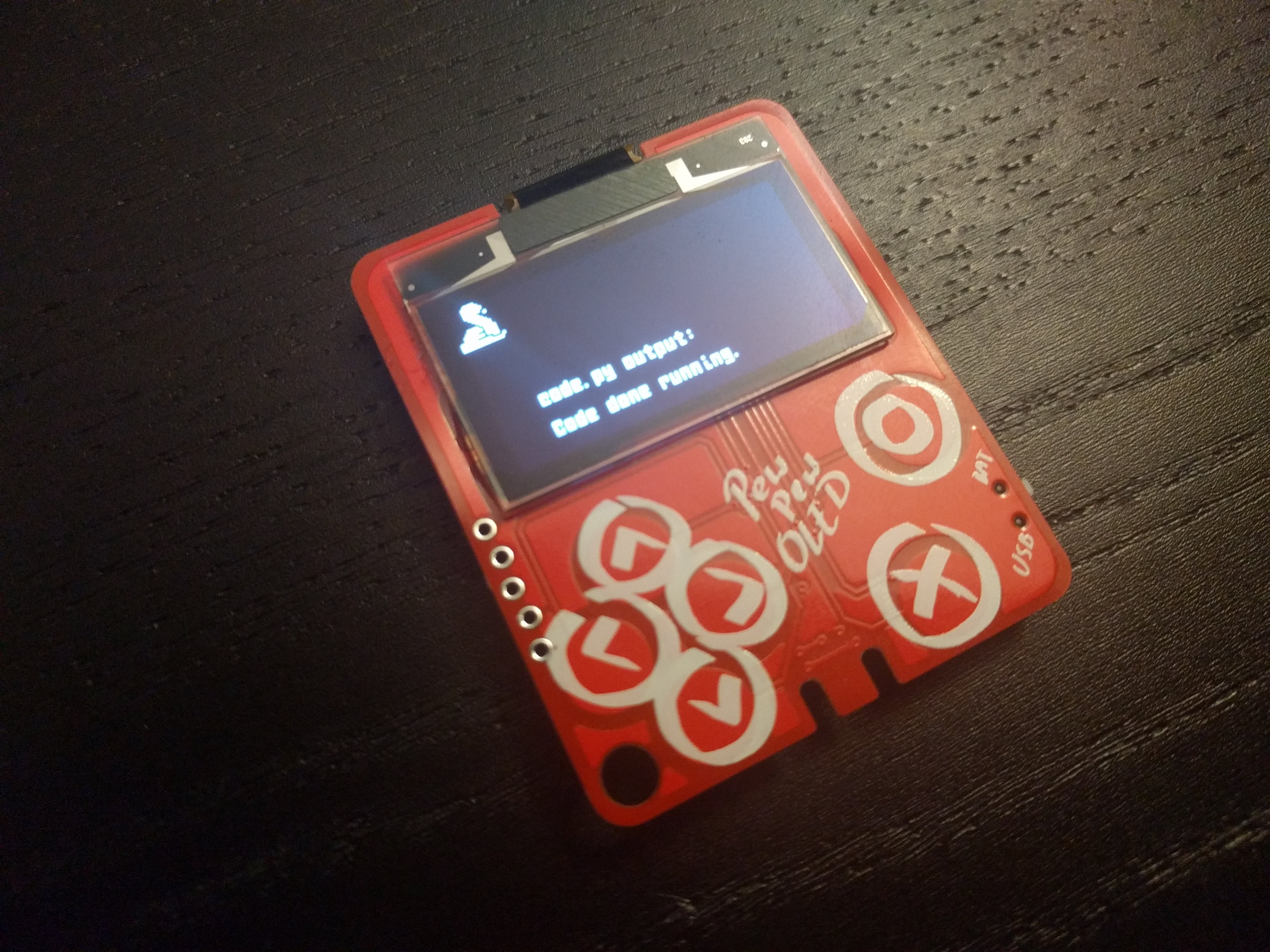
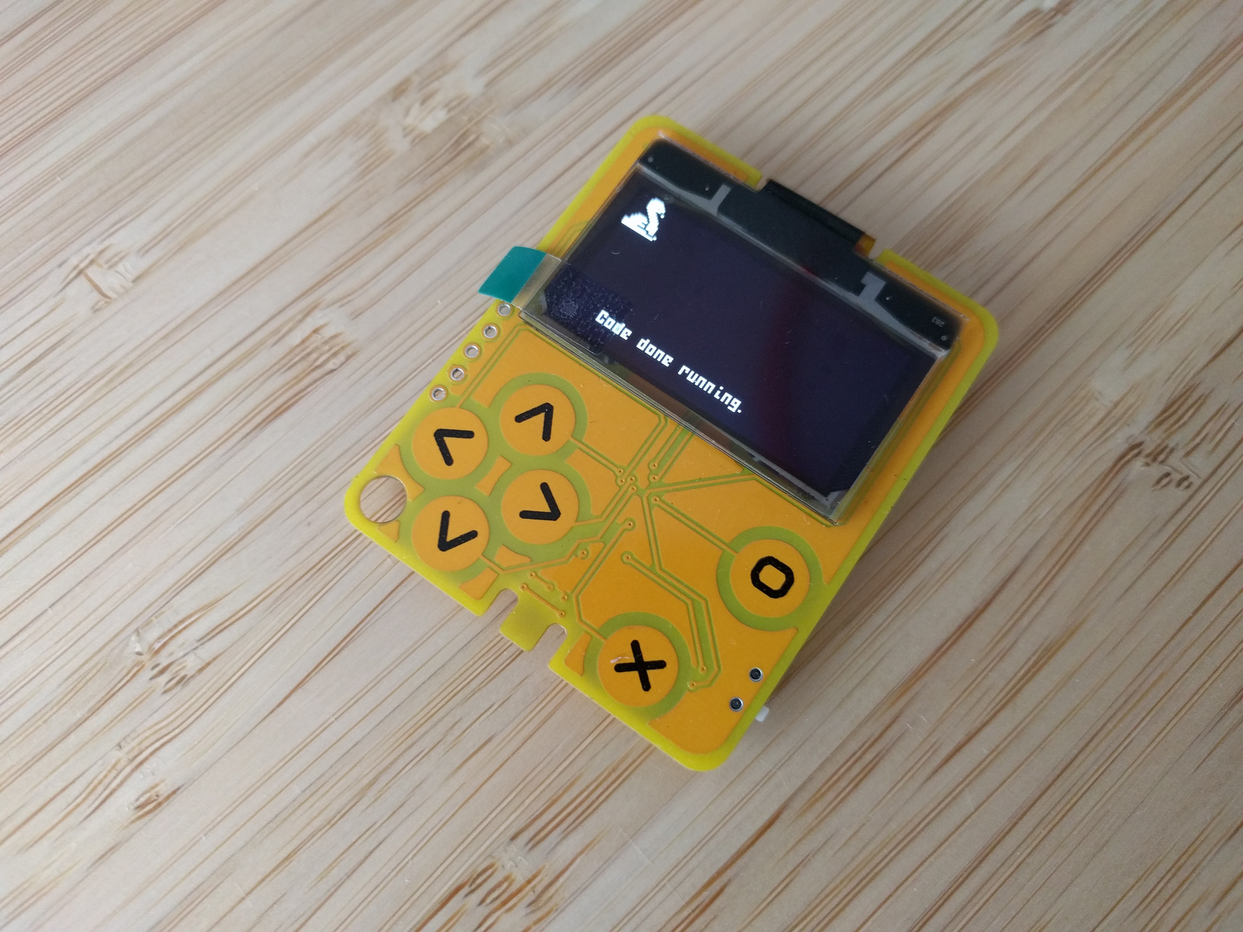
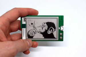
Black-and-white graphics for games has its appeal, so I decided to revisit a prototype that I first made back in 2018 and a year later even managed to get the PewPew games to run on it.

But of course there needs to be some innovation and a challenge, so I decided to change two things:

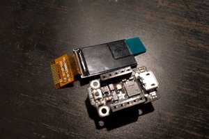
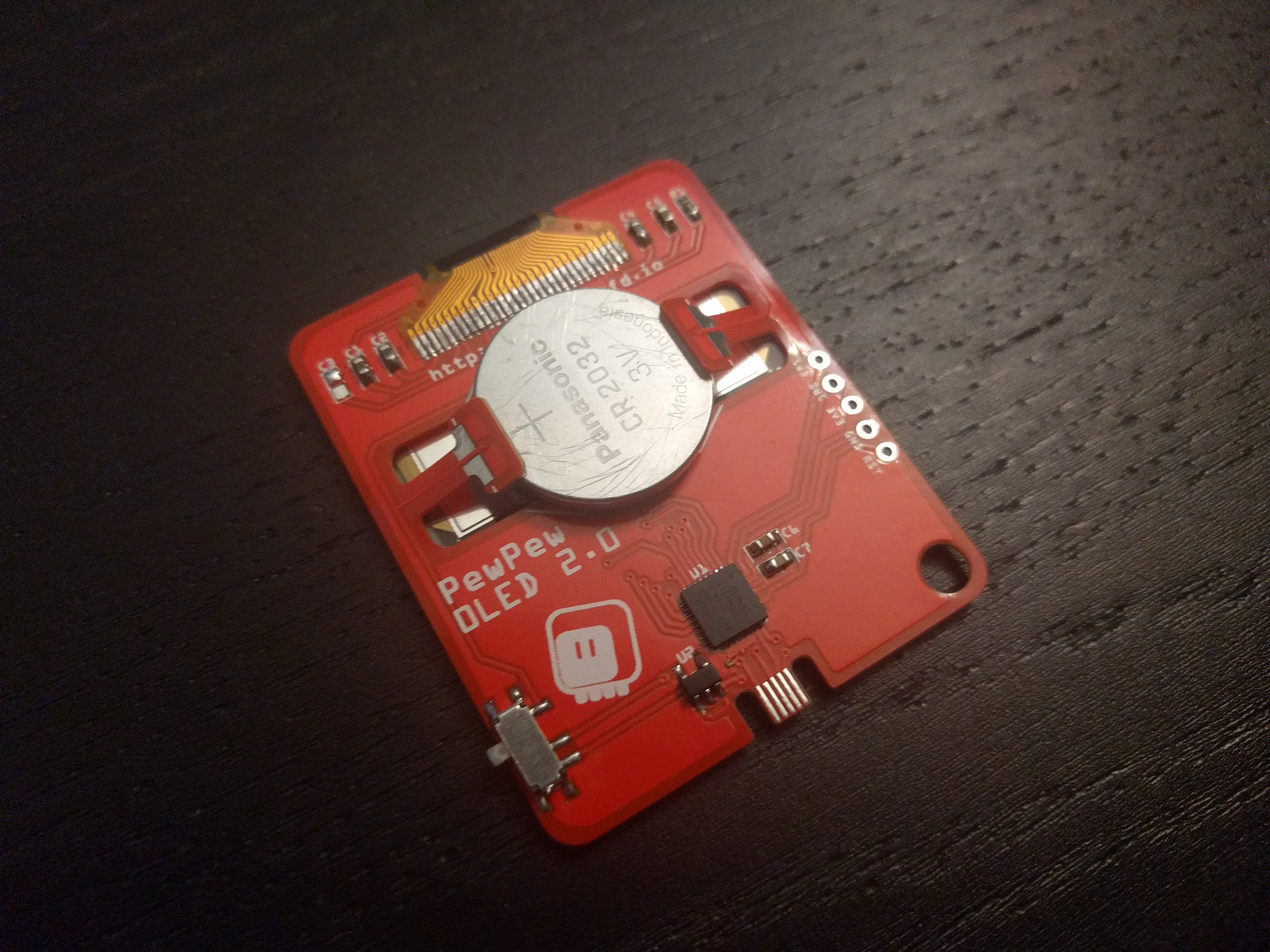
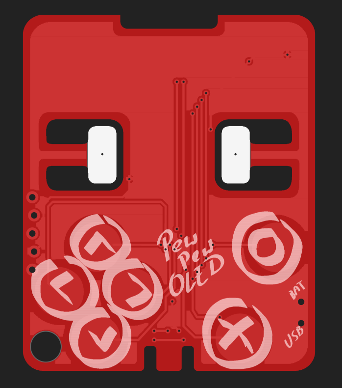
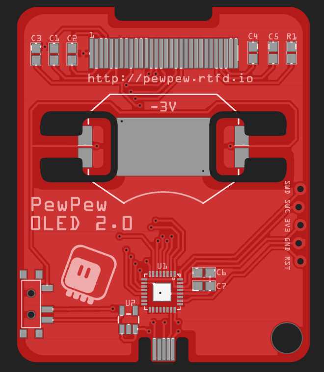
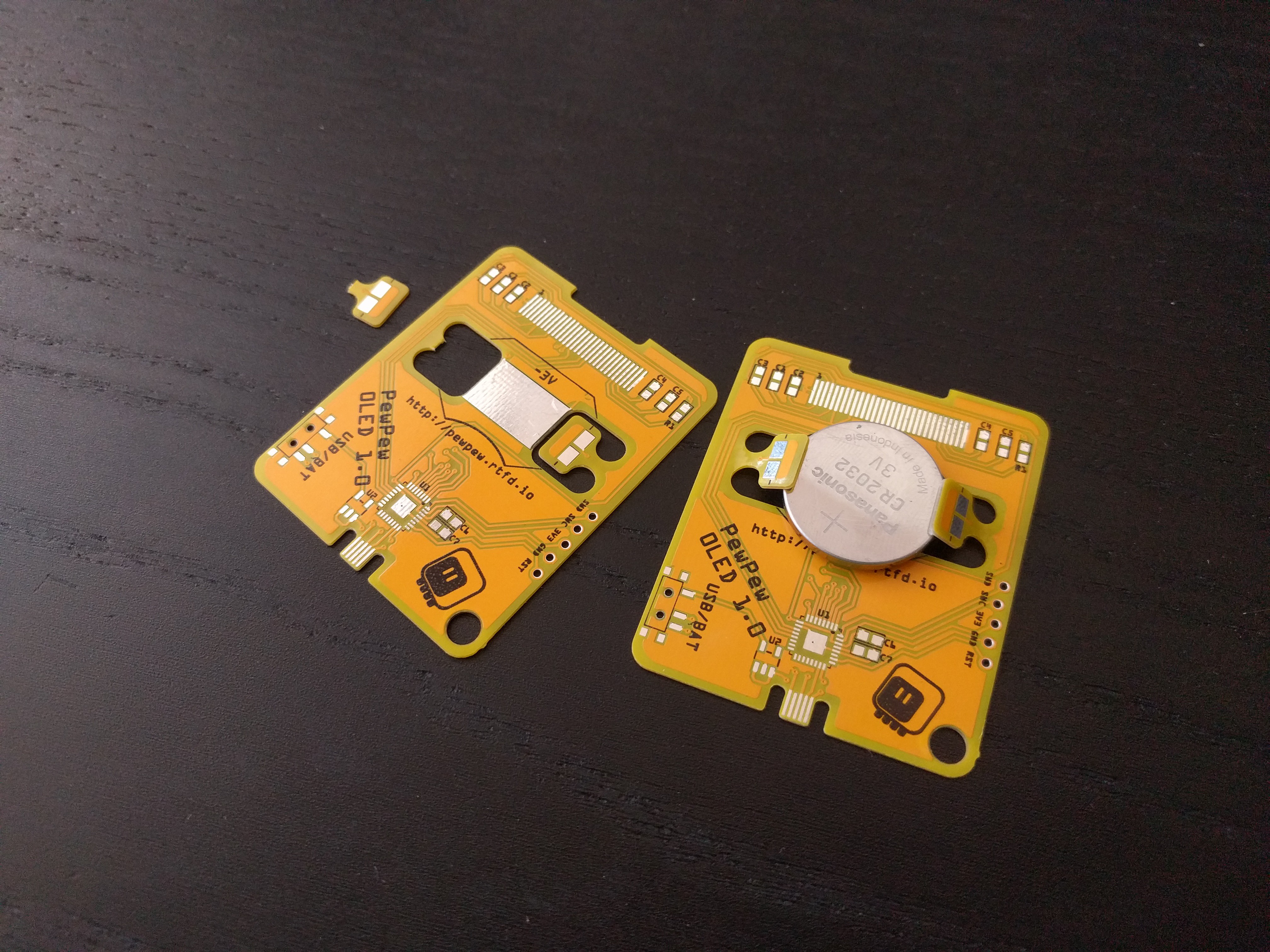
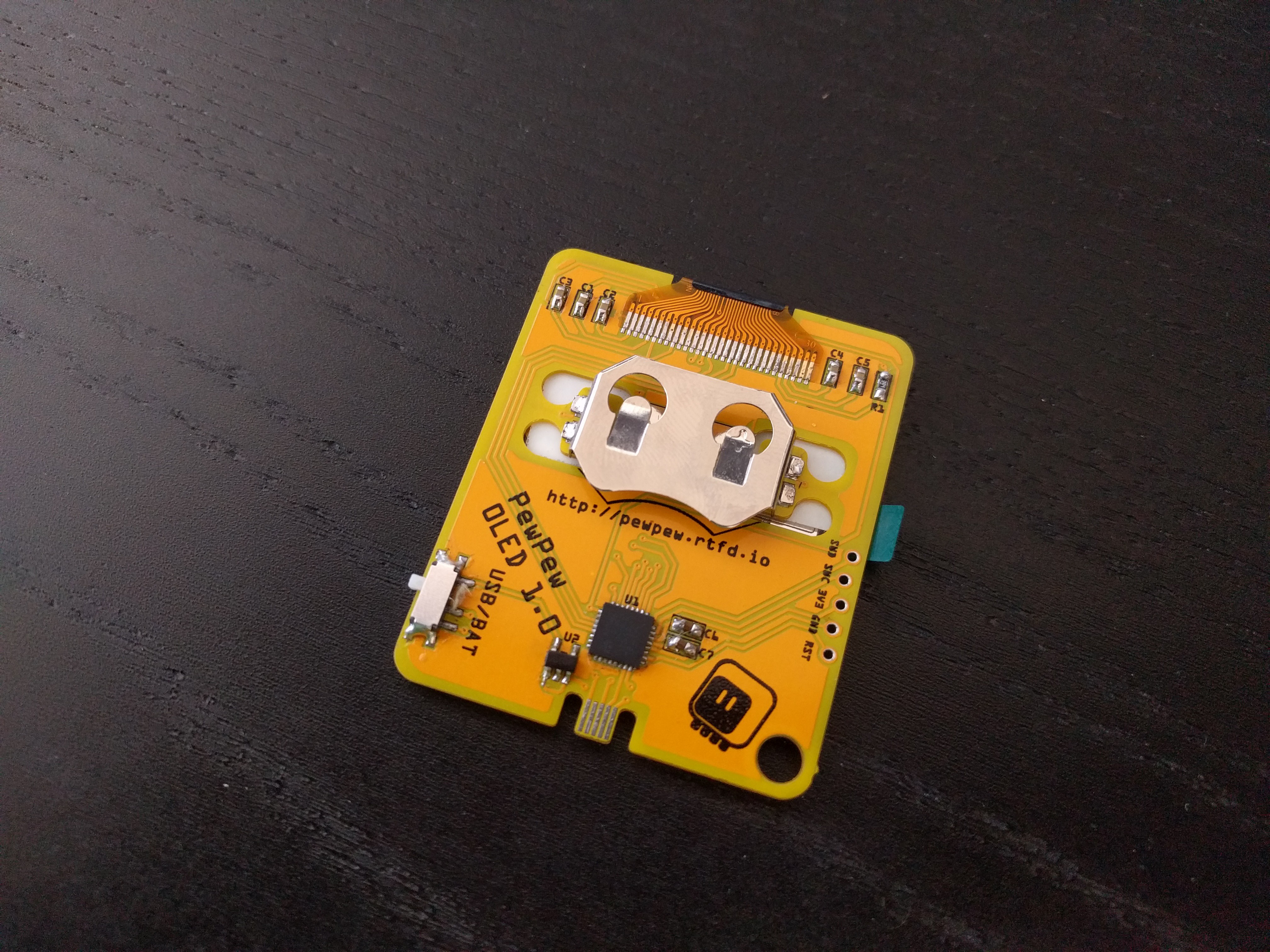
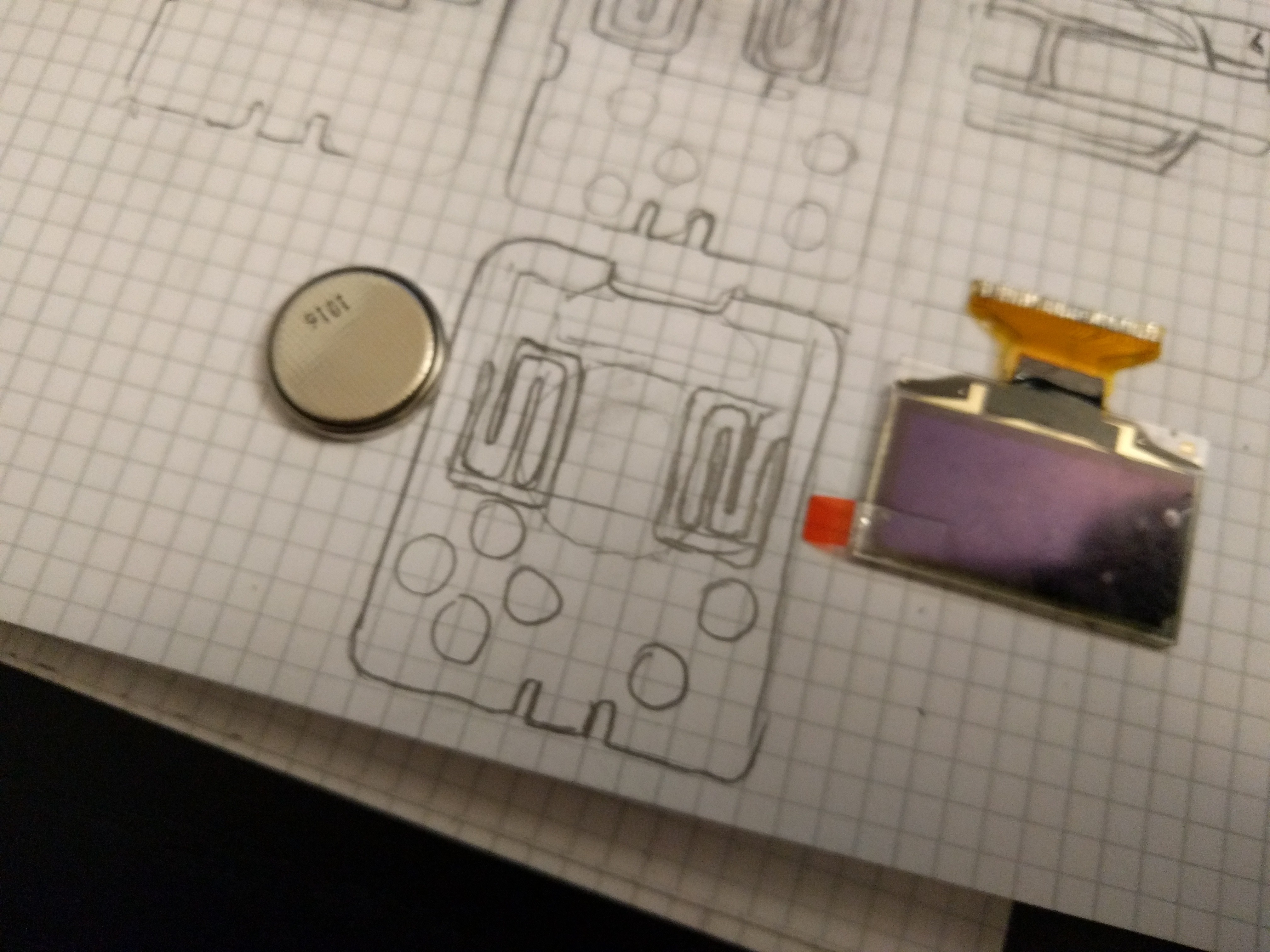
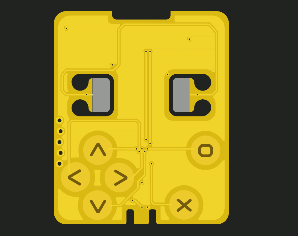
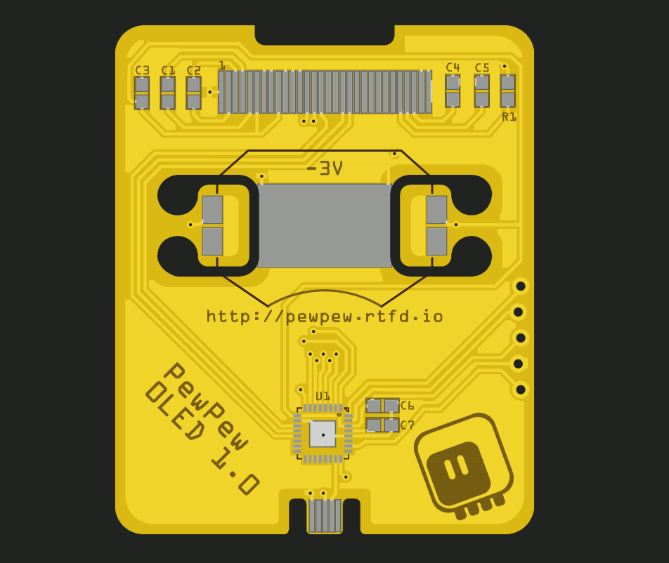
  1. make the hardware design even more minimal, with most parts, such as the buttons, the USB socket or the battery holder simply made out of the PCB itself, and
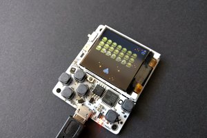
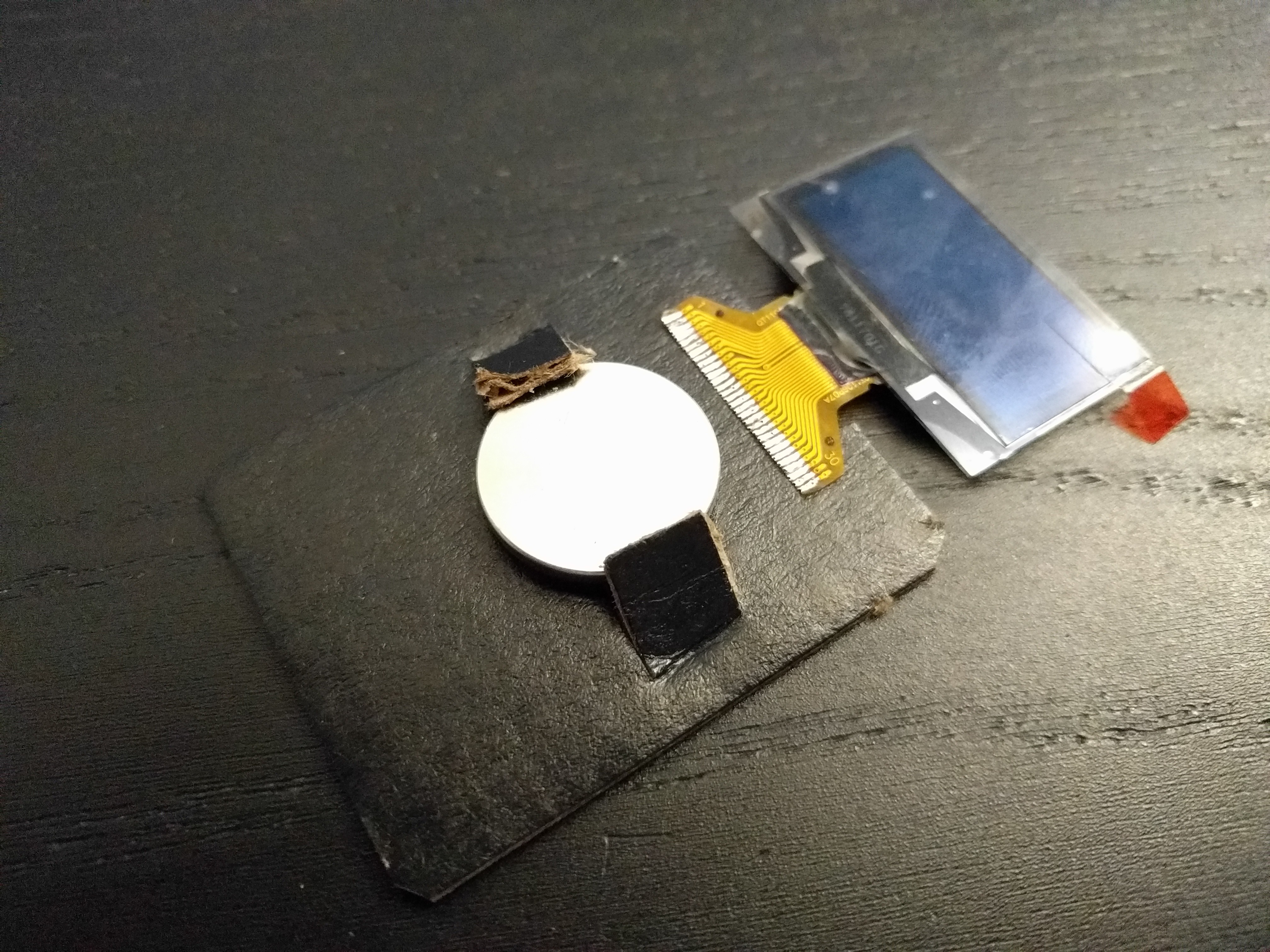
  2. develop a CircuitPython library for the OLED displays similar to #Stage, a Tile and Sprite Engine, but optimized for monochromatic games.

And of course that also means some new games will need to be written, to make sure that the library is usable.

Zip Archive - 106.46 kB - 07/08/2021 at 21:14

Download

pewpew-oled-v2.fzz

Fritzing PCB design

x-fritzing-fzz - 183.39 kB - 07/08/2021 at 21:14

Download

  • Great Success

    deʃhipu07/08/2021 at 20:37 0 comments

    Version two has the battery holder tabs longer, and they work just right without breaking!

    I also left out one of the capacitors — I guess the displays works without filtering its power.

    The latest CircuitPython flashed, now time to write some sprite libraries.

  • Version 2

    deʃhipu06/23/2021 at 09:41 0 comments

    Second attempt, with longer battery tabs — so they will hopefully have enough flex in them to hold the battery without breaking. I also had to re-route some traces, as there wasn't enough room around the holes anymore. Finally, I added fancier silkscreen on the front. I'm thinking this time I will use a red PCB, so that the traces are not so apparent on the front.

  • The pew Library

    deʃhipu06/15/2021 at 13:58 0 comments

    At the heart of every PewPew device is the pew Python library, which gives you access to the 8x8 screen and buttons. That library is different on different devices, but gives your code a consistent interface, so that a PewPew game written on one device will work on any other. I already had a version of the pew library for the SH1106 OLED screen, but it was written before displaio had support for those screens, and just talks to the screen directly over SPI.

    This time I wanted to use the higher-level capabilities of displayio — mostly because then when your program raises an exception, you can see it on the screen and read the error without having to use the serial connection. Unfortunately, doing it the naive way, by using TileGrid, would be too slow. So I went for a kind of compromise — I still generate the data to be sent to the display myself, but then I use the FourWire bus object on the board.DISPLAY to send that data to the display:

    def show(pix):
        pix_buffer = pix.buffer
        bus = board.DISPLAY.bus
        for y in range(8):
            pix_index = pix.width * y
            index = 0
            board.DISPLAY.bus.send(0x0a, b'')
            board.DISPLAY.bus.send(0x11, b'')
            for x in range(8):
                bus.send(0xb0|y, _PATTERNS[pix_buffer[pix_index]])
                index += 10
                pix_index += 1

    The 0x0a and 0x11 commands send the column to 24 (to center the image), and the 0xb0|y command sets the row to the value of y. Then I just keep sending the pre-defined pattern data for the current pixel, in chunks of 10 bytes. Simple yet effective.

    Of course now all the PewPew games will work on this device.

  • Adding Display Initialization to the Firmware

    deʃhipu06/12/2021 at 18:46 0 comments

    Last time we got the CircuitPython firmware running on the device, but the display initialization code was all in Python. Today we are going to move it all into the firmware, so the device starts with the display initialized.

    We will be putting our initialization code into the board.c file, and it looks like this:

    #include "supervisor/board.h"
    
    #include "shared-bindings/board/__init__.h"
    #include "shared-bindings/displayio/FourWire.h"
    #include "shared-module/displayio/__init__.h"
    #include "shared-module/displayio/mipi_constants.h"
    #include "shared-bindings/busio/SPI.h"
    
    displayio_fourwire_obj_t board_display_obj;
    
    #define DELAY 0x80
    
    uint8_t display_init_sequence[] = {
        0xae, 0, // sleep
        0xd5, 1, 0x80, // fOsc divide by 2
        0xa8, 1, 0x3f, // multiplex 64
        0xd3, 1, 0x00, // offset 0
        0x40, 1, 0x00, // start line 0
        0xad, 1, 0x8b, // dc/dc on
        0xa0, 0, // segment remap = 0
        0xc0, 0, // scan incr
        0xda, 1, 0x12, // com pins
        0x81, 1, 0xff, // contrast 255
        0xd9, 1, 0x1f, // pre/dis-charge 2DCLKs/2CLKs
        0xdb, 1, 0x20, // VCOM deslect 0.770
        0x20, 1, 0x20,
        0x33, 0, // VPP 9V
        0xa6, 0, // not inverted
        0xa4, 0, // normal
        0xaf, 0, // on
    };
    
    void board_init(void) {
        busio_spi_obj_t *spi = &displays[0].fourwire_bus.inline_bus;
        common_hal_busio_spi_construct(spi, &pin_PA09, &pin_PA08, NULL);
        common_hal_busio_spi_never_reset(spi);
    
        displayio_fourwire_obj_t *bus = &displays[0].fourwire_bus;
        bus->base.type = &displayio_fourwire_type;
        common_hal_displayio_fourwire_construct(bus,
            spi,
            &pin_PA10, // Command or data
            &pin_PA01, // Chip select
            &pin_PA00, // Reset
            1000000, // Baudrate
            0, // Polarity
            0); // Phase
    
        displayio_display_obj_t *display = &displays[0].display;
        display->base.type = &displayio_display_type;
        common_hal_displayio_display_construct(display,
            bus,
            128, // Width
            64, // Height
            2, // column start
            0, // row start
            0, // rotation
            1, // Color depth
            true, // grayscale
            false, // pixels in byte share row. Only used with depth < 8
            1, // bytes per cell. Only valid for depths < 8
            false, // reverse_pixels_in_byte. Only valid for depths < 8
            true, // reverse_pixels_in_word
            0, // Set column command
            0, // Set row command
            0, // Write memory command
            0xd3, // set vertical scroll command
            display_init_sequence,
            sizeof(display_init_sequence),
            NULL,
            0x81,
            1.0f, // brightness
            false, // auto_brightness
            true, // single_byte_bounds
            true, // data as commands
            true, // auto_refresh
            60, // native_frames_per_second
            true, // backlight_on_high
            true); // SH1107_addressing
    }
    
    bool board_requests_safe_mode(void) {
        return false;
    }
    
    void reset_board(void) {
    }

     This is basically copied from pygamer's board.c, with the initialization sequence and the display arguments copied from the SH1106 driver code. There are, however, three changes I made.

    First of all, of course I had to change which pins are being used — this is pretty straightforward.

    Then, I had to rotate my display up-side-down. I could have done this with the "rotation" argument of the display, but I want to write some code that writes to the display directly, so I really wanted to rotate it in its initialization. This is what the "segment remap" and "scan direction" registers are for, and I changed them both to 0.

    Finally, the way the displays I got are constructed, the first two columns are not connected, so I set "column start" to 2, to compensate for that.

    After compiling and flashing this, and removing the Python code from the last time, I get a working display. I also tested that it works powered from a CR2032 battery.

  • Adding the board to CircuitPython

    deʃhipu06/12/2021 at 18:33 0 comments

    Last time I went all the way up to flashing an UF2 bootloader on the SAMD21 chip, now we need to get CircuitPython running on it. Normally I would just use the firmware for #Fluff M0 — it has all the pins available, so it's very convenient for such things, but this time we are going to need the displayio module compiled into the firmware, and later we will also add the display initialization, so that the display just works as soon as the device is switched on, without us having to initialize it in our own code.

    To add a new SAMD board, the easiest way is to copy an existing board definition, like the fluff_m0 one, in ports/atmel-samd/boards, and rename it. Then we can edit the files to make our changes:

    mpconfigboard.h

    #define MICROPY_HW_BOARD_NAME "PewPew OLED"
    #define MICROPY_HW_MCU_NAME "samd21e18"
    
    #define MICROPY_PORT_A        (0)
    #define MICROPY_PORT_B        (0)
    #define MICROPY_PORT_C        (0)
    
    #define CIRCUITPY_INTERNAL_NVM_SIZE 0
    #define CIRCUITPY_INTERNAL_FLASH_FILESYSTEM_SIZE (48 * 1024)
    
    // USB is always used internally so skip the pin objects for it.
    #define IGNORE_PIN_PA24     1
    #define IGNORE_PIN_PA25     1
    
    #define SAMD21_BOD33_LEVEL (6)

    There are three noteworthy things here. We change the NVM size to 0 (this is a part of the flash reserved for storing additional information,  we are not going to be using that), and the filesystem size to 48kB (from the default of 64kB). This is needed to make more room for the firmware in the flash, because we want to include displayio, which is quite big.

    Finally, the SAMD21_BOD33_LEVEL variable controls the brown-out detection voltage level. We need to set it as low as practical, so that our device can work from a puny 3V battery without going into safe mode.

    Later on we can add all the pins we are not using on the device, to save some RAM. It's not important right now.

    pins.c

    #include "shared-bindings/board/__init__.h"
    
    STATIC const mp_rom_map_elem_t board_global_dict_table[] = {
        { MP_ROM_QSTR(MP_QSTR_SCK), MP_ROM_PTR(&pin_PA09) },
        { MP_ROM_QSTR(MP_QSTR_MOSI), MP_ROM_PTR(&pin_PA08) },
        { MP_ROM_QSTR(MP_QSTR_OLED_DC), MP_ROM_PTR(&pin_PA10) },
        { MP_ROM_QSTR(MP_QSTR_OLED_CS), MP_ROM_PTR(&pin_PA01) },
        { MP_ROM_QSTR(MP_QSTR_OLED_RESET), MP_ROM_PTR(&pin_PA00) },
    
        { MP_ROM_QSTR(MP_QSTR_TOUCH_UP), MP_ROM_PTR(&pin_PA02) },
        { MP_ROM_QSTR(MP_QSTR_TOUCH_DOWN), MP_ROM_PTR(&pin_PA05) },
        { MP_ROM_QSTR(MP_QSTR_TOUCH_LEFT), MP_ROM_PTR(&pin_PA03) },
        { MP_ROM_QSTR(MP_QSTR_TOUCH_RIGHT), MP_ROM_PTR(&pin_PA04) },
        { MP_ROM_QSTR(MP_QSTR_TOUCH_O), MP_ROM_PTR(&pin_PA06) },
        { MP_ROM_QSTR(MP_QSTR_TOUCH_X), MP_ROM_PTR(&pin_PA07) },
    
    };
    MP_DEFINE_CONST_DICT(board_module_globals, board_global_dict_table);

    This defines which pins on the microcontroller are used for what.

    mpconfigboard.mk

    USB_VID = 0x239A
    USB_PID = 0x80B0
    USB_PRODUCT = "PewPew OLED"
    USB_MANUFACTURER = "Radomir Dopieralski"
    
    CHIP_VARIANT = SAMD21E18A
    CHIP_FAMILY = samd21
    
    INTERNAL_FLASH_FILESYSTEM = 1
    LONGINT_IMPL = NONE
    
    CIRCUITPY_FULL_BUILD = 0
    
    CIRCUITPY_DISPLAYIO = 1
    CIRCUITPY_TOUCHIO = 1
    
    CIRCUITPY_ANALOGIO = 0
    CIRCUITPY_AUDIOBUSIO = 0
    CIRCUITPY_AUDIOBUSIO_I2SOUT = 0
    CIRCUITPY_AUDIOCORE = 0
    CIRCUITPY_AUDIOIO = 0
    CIRCUITPY_AUDIOMIXER = 0
    CIRCUITPY_AUDIOMP3 = 0
    CIRCUITPY_AUDIOPWMIO = 0
    CIRCUITPY_BITBANG_APA102 = 0
    CIRCUITPY_BITBANGIO = 0
    CIRCUITPY_BITBANGIO = 0
    CIRCUITPY_BITMAPTOOLS = 0
    CIRCUITPY_BITMAPTOOLS = 0
    CIRCUITPY_BLEIO = 0
    CIRCUITPY_BUSDEVICE = 0
    CIRCUITPY_FRAMEBUFFERIO = 0
    CIRCUITPY_FREQUENCYIO = 0
    CIRCUITPY_GAMEPAD = 0
    CIRCUITPY_GAMEPADSHIFT = 0
    CIRCUITPY_I2CPERIPHERAL = 0
    CIRCUITPY_MATH = 0
    CIRCUITPY_MSGPACK = 0
    CIRCUITPY_NEOPIXEL_WRITE = 0
    CIRCUITPY_NVM = 0
    CIRCUITPY_PIXELBUF = 0
    CIRCUITPY_PS2IO = 0
    CIRCUITPY_PULSEIO = 0
    CIRCUITPY_PWMIO = 0
    CIRCUITPY_RGBMATRIX = 0
    CIRCUITPY_ROTARYIO = 0
    CIRCUITPY_ROTARYIO = 0
    CIRCUITPY_RTC = 0
    CIRCUITPY_SAMD = 0
    CIRCUITPY_ULAB = 0
    CIRCUITPY_USB_HID = 0
    CIRCUITPY_USB_MIDI = 0
    CIRCUITPY_USB_VENDOR = 0
    CIRCUITPY_VECTORIO = 0
    
    CIRCUITPY_DISPLAY_FONT = $(TOP)/ports/atmel-samd/boards/ugame10/brutalist-6.bdf
    OPTIMIZATION_FLAGS...
    Read more »

  • First Prototype Failure

    deʃhipu06/11/2021 at 22:02 0 comments

    The boards finally arrived, and I got a chance to test the battery holder:

    The tabs can just barely be lifted enough to insert the coin cell in place, but it's extremely easy to break them. On the other hand, they hold the battery in place quite well, so I think this will work, I just need to make the thin parts of the tabs much longer.

    Having tested that part, I went ahead and assembled one board, with a regular battery holder this time:

    I have the bootloader flashed, now I need to prepare the board definition for CircuitPython and get display to work on it.

  • Designing the Battery Holder

    deʃhipu06/11/2021 at 21:57 0 comments

    Touch buttons and a USB socket are relatively easy to make, and I did them before. But a battery holder is a new thing, and it requires some thought. I made a number of sketches:

    But eventually I decided to got with the simplest possible design that just might work:

    Here is how it's supposed to work:

    I'm not entirely sure how elastic the PCB will be, and how much I will need to bend it, so I assume some experimenting will be needed. I started with relatively short but thin tabs. I also included a footprint for a regular battery holder on top of it, so that if my first design doesn't work, I can still use the boards to test and prototype other parts.

View all 7 project logs

Enjoy this project?

Share

Discussions

Similar Projects

Does this project spark your interest?

Become a member to follow this project and never miss any updates