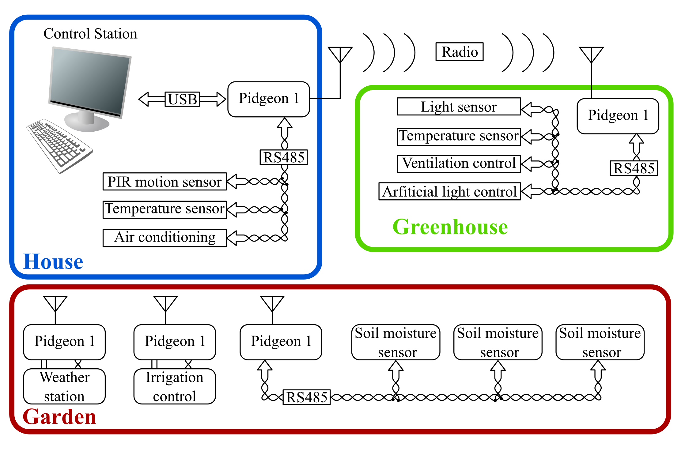
Aim of the device is to allow access to the RF spectrum at elementary level to any desktop computer. Expansion of computer connectivity into 868MHz or 915MHz bands improves desktop engagement in "Internet of Things" applications.
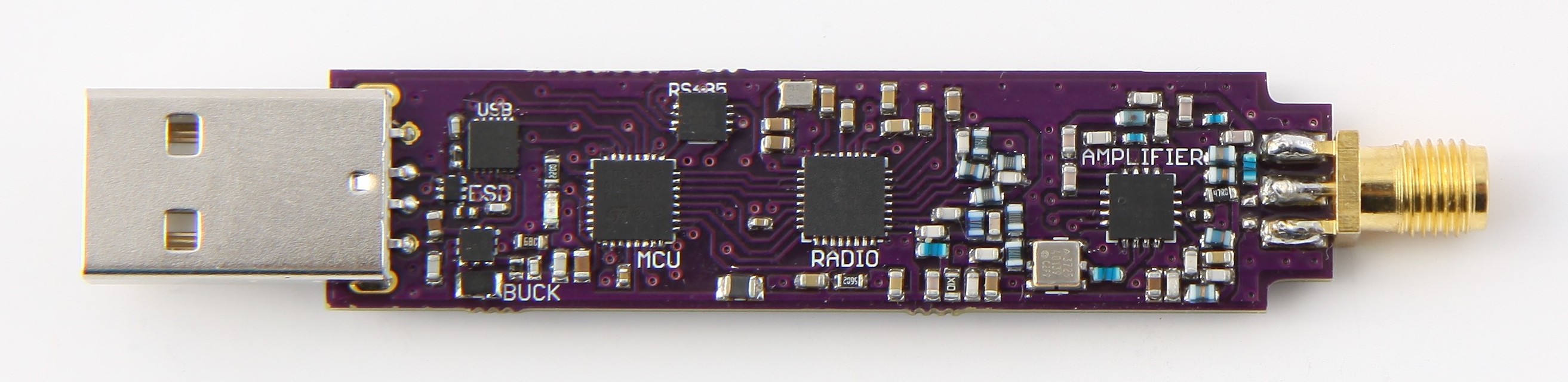
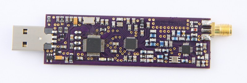
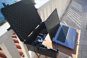
Device offers 3 interfaces :
- USB connector used to connect to the host PC, where device is recognized as a virtual COM port.
- SMA connector for RF input ( antenna ).
- RS485 interface
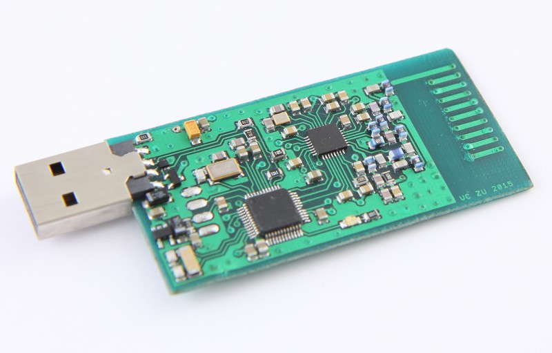
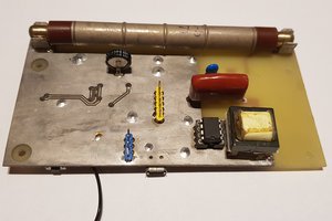
Radio
Device uses CC1120 for RF
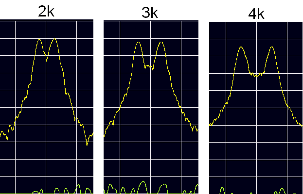
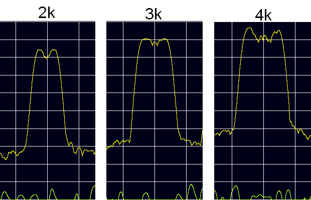
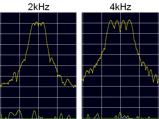
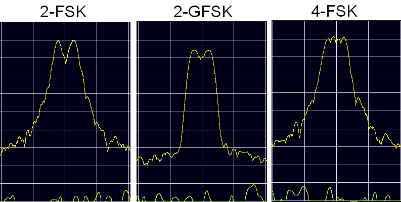
signal handling. The most notable properties of this IC are – narrow bandwidth, many types of modulations (including 4 state
ones), 128 byte FIFO, good sensitivity and more. See all properties
at manufacturer website.
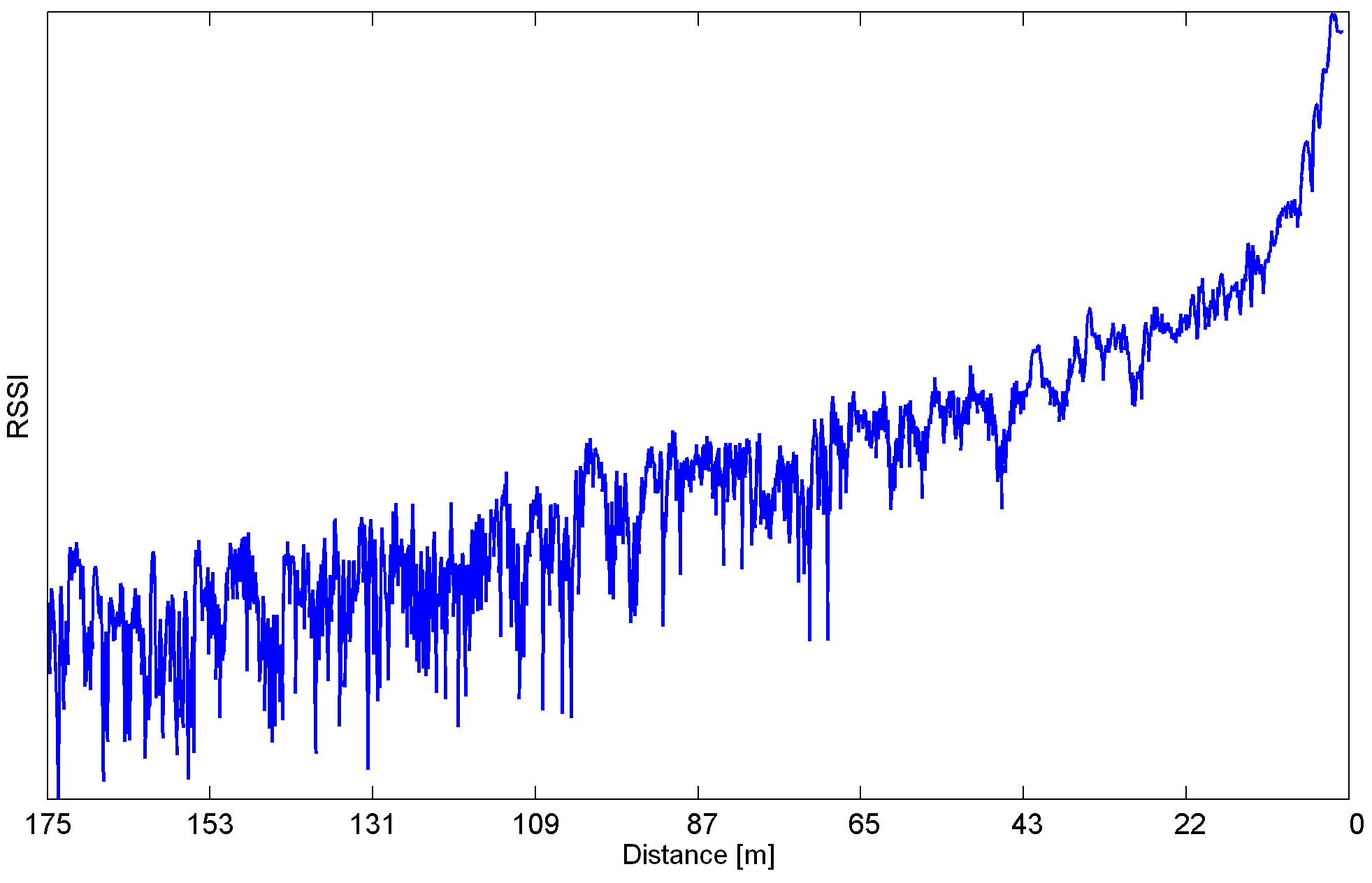
This IC is not the cheapest on the market, but it offers many useful features. Together with CC1190 front end they achieve range sufficient for most applications. Tested range of the device at handheld height with simple wire antenna and a tree in line-of-sight is 500meters at 4,8kpbs with 25khz bandwidth.
Controller
STM32F0 microcontroller is chosen to be the brain of the device. This MCU uses power-efficient Cortrex-M0 core which is well suited for event driven workload. USB stack is implemented externally via FTDI chip which assures good compatibility and keeps the programming beginner friendly. User’s code is debugged over SWD interface which means the user needs ST-link for debugging ( any ST’s discovery kit would do ). In theory user can program the device via USB port (just program, not debug! ).
Device is tested to work on Windows and Linux machines, including distributions for ARM architecture*. Which means this device can help you connect to your remote Raspberry Pi. You can also use SLIP or PPP protocols to allow this link to extend slow internet access over great line-of-sight range.
* – Tested to work for Raspbian (Raspberry Pi 3) and Debian (A20-OlinuXino-Lime).


 Marek Więcek
 mircemk
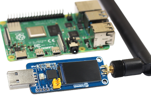
In my opinion, the easiest way to popularize this device is to run a network on it https://reticulum.network/index_pl.html . KISS or PIPE should be easy.