This project was developed in partnership with Robô Lúdico School and JLCPCB Factory that offers 5 free PCBs of Arduino Compatible Board.
Introduction to autonomous mobile robots
In this project, you will learn how to assemble your first autonomous mobile robot with a movable axis. Autonomous mobile robots are essential in a variety of activities.
Several companies use these autonomous robots to explore environments inaccessible to humans, access to dangerous terrains, and other activities.
In addition to serving in all these activities, autonomous mobile robots can assist in the development of education for children and young people in the world of programming and electronics.
Now you will learn how to build the structure of this autonomous mobile robot with wheels.
This mobile robot is controlled through the Arduino UNO, which processes the signal from the sensors and user control. In addition, it drives the motors of the robot's wheels.
Now, see what you will learn.
- Understand how the structure of an autonomous mobile robot with wheels works;
- Understand the functioning of the mobile axis of the mobile robot with wheels with SG90 servo motor;
- How the Arduino performs the reading of the sensors and control of the motors of the mobile robot with wheels;
- The interlocking mechanisms of the robot's structure and the operation of its movable axis with the servo-motor;
- The operating logic of the mobile robot with turn control.
Let's get started?
The process of building a mobile robot
Most mobile robots with wheels are not able to perform cornering movements.
This limitation exists because these mobile robots do not have a movable axle on the front wheels of the robot. In this project, you will learn how to solve this problem and create a movable axle for your mobile robot with wheels.
See, in the photo below, the structure of the robot's movable axis. You will learn the constructive structure and how it worksonthe movable axis of the mobile robot.

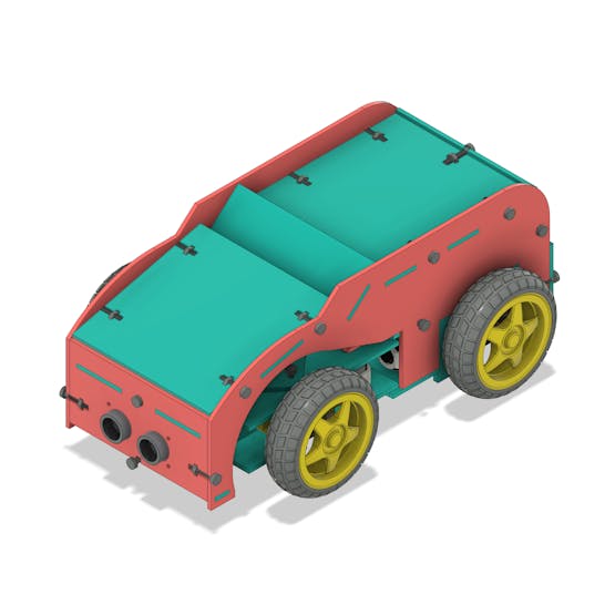
The structure of the mobile robot is shown below.

As already mentioned, this mobile robot has a movable axis, which allows us to make curves. Its structure was developed with 2.5 mm MDF material, but you can use any material with the same thickness.
This autonomous mobile robot consists of the following parts:
- Arduino UNO;
- Ultrasonic sensor to detect obstacles;
- DC motors with 4 wheels;
- Servo motor to control the movement of the shaft;
- Space for Bluetooth module.
The Arduino is the control board that is responsible for controlling the motors and reading the signal from the ultrasonic sensor of the mobile robot.

It was positioned in the rear region of the robot, to facilitate the programming of the robot and changes in the code. This prevents the user from removing the Arduino.
Figure 8 shows the Arduino installed in the autonomous mobile robot.

The control board is shown below and has the Arduino UNO format. All sensors and drive drivers will be connected in their structure.
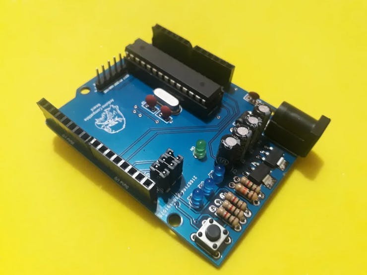
The control board is responsible for receiving control commands via Bluetooth or sensors. Based on the information received, it will activate the drivers so that the motors can move the robot in a certain direction.
Did you win the files on that board? Follow this process and get 5 free units. It is easy to assemble!
You must follow all of these steps below.
- Download the robot control board file
- Enter in this website and make your account.
- Add the control board files to the website
- Add the JLC-REBE discount coupon to the payment section
- Ready, you won 5 free PCB units.
It sends a signal to trigger the ultrasonic sensor and does the calculation to determine the distance. After that, it allows the mobile robot to move forward the DC Motors or change direction to avoid a possible obstacle.
The DC motors are connected to the L293D driver circuit.
This driver can control the speed of the wheels through the PWM signal, as well as their direction of rotation.
The driver was installed on the inner rear surface, close to the engines, as shown in Figure 4.

In addition to controlling the driver driving the DC motors, the Arduino controls the SG90 servo motor. The SG90 servo motor is responsible for controlling the car's rotation.
Through this motor, it is possible to control the direction (left and right) of the mobile robot.
This servomotor has three pins: a 5-volt pin (VCC), a ground pin (GND), and a control pin (PWM).
The control of rotation is based on the duty cycle (time of high logic level in a determined period of time) that is sent by the Arduino to the pin of the servomotor, that when receiving this signal, will make the axis of rotation to be at the desired angle through the developed programming.
When the signal is sent, the servomotor will cause the vehicle to turn to the right or to the left, using the turning mechanism illustrated in Figure 5.

The mechanism responsible for the rotation of the mobile robot consists of the disk connected to the servomotor and the axis that connects the two front motors.
The connection point between the rotating disc and the shaft has a small disc to compensate for the space between these components. This helps to decrease the clearance.
As the servo-motor rotates left or right, the connection point between the disc and the axle will move the front motors, in order to change the direction of the mobile robot. Figure 6 illustrates the displacement mentioned.

Figure 9 shows the structure of the autonomous mobile robot in an exploded perspective.

This is the complete structure of the autonomous mobile robot that can be used in different applications.
Conclusion
The main highlight of this robot is its movable axis. Analyzing its structure, it was possible to observe that the robot presented greater mobility and better control for curves and movements in other directions.
In the next projects we will present the complete structure of the programming logic with the control board below.
The control board is responsible for receiving control commands via Bluetooth or sensors. Based on the information received, it will activate the drivers so that the motors can move the robot in a certain direction.
Did you win the files on that board? Follow this process and get 5 free units. It is easy to assemble!
You must follow all of these steps below.
- Download the robot control board file
- Enter in this website and make your account.
- Add the control board files to the website
- Add the JLC-REBE discount coupon to the payment section
- Ready, you won 5 free PCB units.