 Zach Baldwin
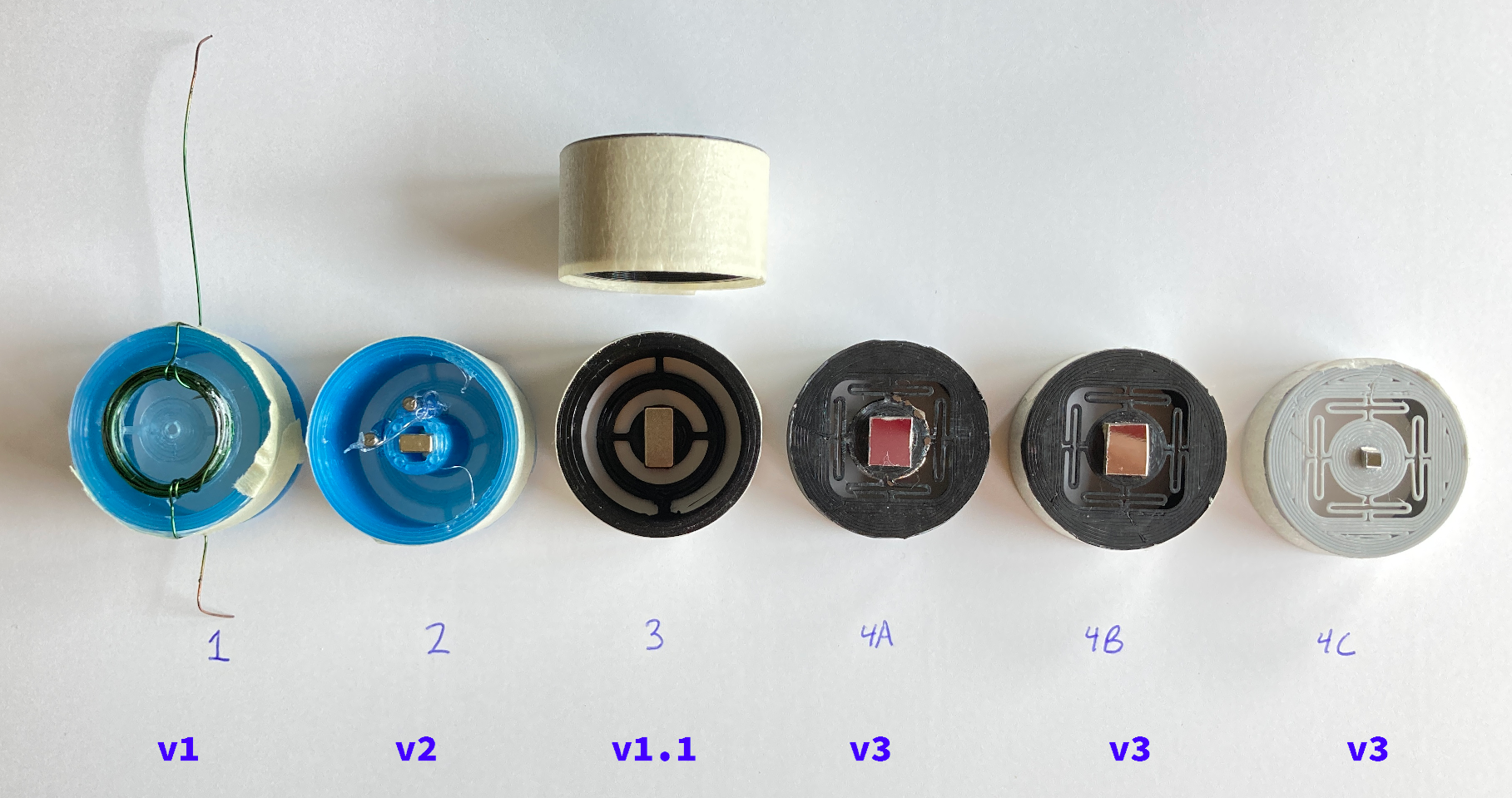
Lots of progress! By about May 29, the above set of gimbals had been developed (with the help of lots of online searching for commercial MEMS mirror designs). The top row of hand-written numbers is the trial number and the bottom row is the gimbal design version. Going in order:
Gimbal 1 - After trying out different nails in the original gimbal design, I decided that the amount of deflection was not going to be as high as I would like. As a result, I took a slight detour and decided to move the coil onto the gimbal and place some magnets on the outside, similar to a motor made with some wire, paperclips, and a battery. The result? Less deflection than the nail inside the yoke, while reintroducing the overheating problem.
Gimbal 2 - I had the realization that by adding magnets to the gimbal, the yoke's force exerted on it would increase because of the field interactions. This design uses two rectangular neodymium magnets fitted into a cylinder under the gimbal (picture is a bottom view). The magnets increased the deflection slightly. To see if adding some metal to the gimbal would help "guide" the magnetic field at all, two nails were hot glued to the outside of the cylinder, parallel to the magnets. This helped tremendously.
At this point, I figured it would be a good test to see what kind of frequency response I could get out of this setup. Since the coil impedances of the yoke (2 and 4 ohms, depending on the coil axis) were similar to that of a typical speaker, an old car stereo was hooked up to drive both the axies. With a waveform generator on my computer (A.K.A. Audacity and onlinetonegenerator.com), I tried out different frequencies of sine waves and found the resonant frequency of the gimbal setup to be around 10Hz. This was much slower than I had hoped, but it was still progress.
It was time to find a mirror for the gimbal, and I knew just the place to get it: the platter of a dead HDD. Taking the Dremel to the platter, I produced a ~6x7mm square which got taped to the gimbal via some rolled masking tape. Combined with a laser pointer, I was able to move the point around with a few inches of deflection at about 5 feet.
Gimbal 3 - In an effort to increase the resonant frequency, I printed another gimbal and this time, used the same rectangular magnets from the second revision. One magnet was placed on either side of the gimbal's central disk and the mirror was stuck to the outside. This new gimbal sandwich gave improved results, providing a better deflection angle and a higher resonant frequency of about 50Hz. One downside to this configuration is that the two axies seem to interfere with each other when there is a rapid change in the yoke's input waveform (i.e. a sawtooth wave). This produces a lot ringing in the reflected laser beam.
(Gimbal 3B) - [Not pictured] Two of the 10mm-diameter magnets (used in 4A) were used to create a sandwich, similar to 3. In the process of feeding the yoke a sine wave, I turned the amplitude up a bit too high and turned the gimbal into a small motor, rotating the magnets around and around for about 10 seconds before the plastic broke. Oops :)
Gimbal 4A - A single, round neodymium magnet was superglued to the bottom of the gimbal disk while a mirror (and some of the table top) was glued to the top of the gimbal. The gimbal design was modified to use "O" shaped springs (found in here), allowing the axies to interfere less, reducing the ringing and providing a nearly identical response out of both axies.
Gimbal 4B - Similar to 4A, however, the large, 10mm-diameter magnet was changed out for one of the previous rectangular magnets that was cut in half to give a 5x5mm magnet. After cutting the magnet, I found that the side that was in the vice still had a strong magnetic field, while the half in open air had about the level of a fridge magnet. Looks like the heat of the cutting process caused some demagnetization. This was the most promising of the gimbals so far, with a resonant frequency somewhere between 200 and 300Hz.
Gimbal 4C - Continuing the idea of reducing the mass of the gimbal, a tiny 2mm square mirror was cut and 4 2mm-diameter magnets were attached to the back of the gimbal. Since the magnets were so small, the amount of power to get the same amount of deflection as 4B was too high for the car stereo. So for now, I will be sticking with 4B.
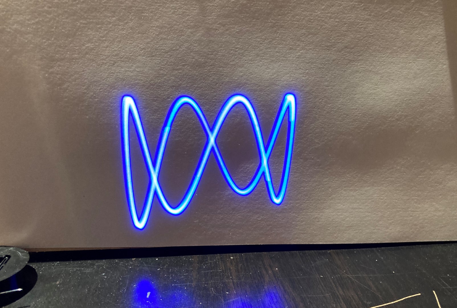
I'll leave you with this picture:
Discussions
Become a Hackaday.io Member
Create an account to leave a comment. Already have an account? Log In.