Close
0%
0%

Not-so-dull free form clock

A smart, connected, free form circuit clock and bedside lamp for sleep scheduling

Similar projects worth following
The lack of routine can make quarantine life difficult for those of us with less self-restraint than we would like. This can be helped with a proper sleep schedule. The purpose of this device is to be an attractive alarm clock that doubles as a bedside lamp, reducing the annoying table clutter. The clock will flash and/or beep before it's time to sleep, and then slowly reduce its brightness before turning off completely. In the morning the clock will turn on and increase in brightness before the first alarm, hopefully reducing the shock of waking up. This could possibly be synchronized with a mobile device using tasker or something similar.

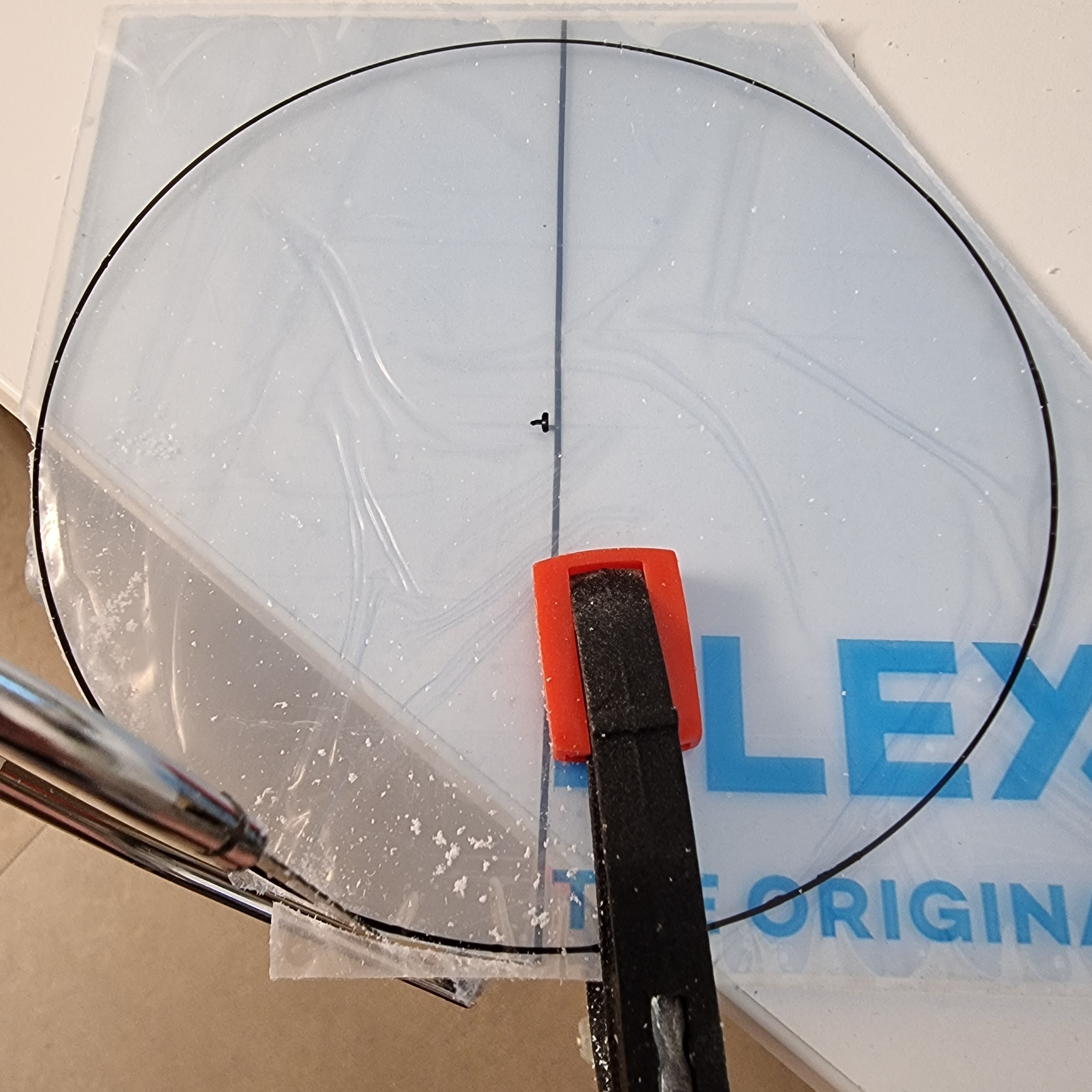
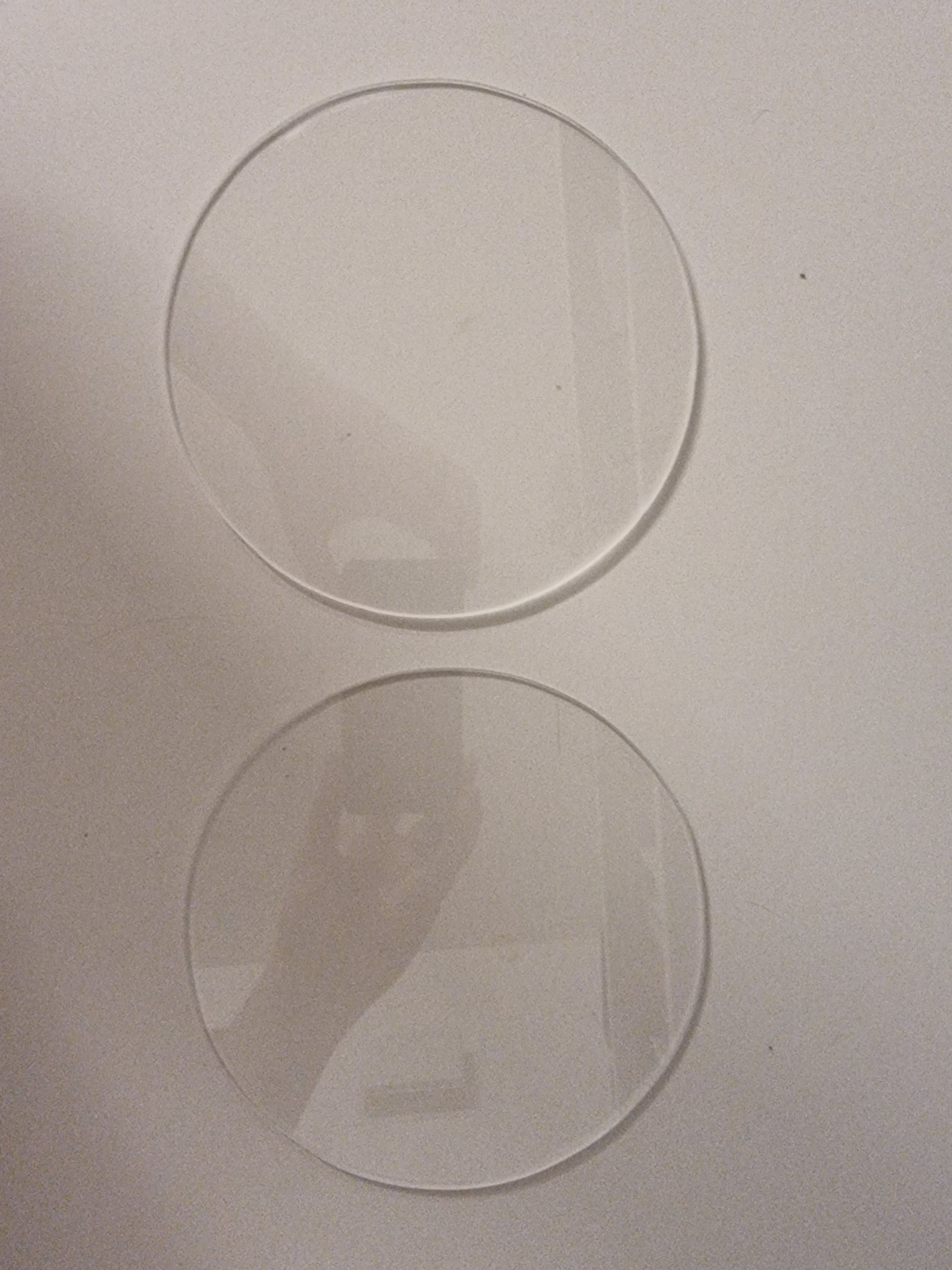
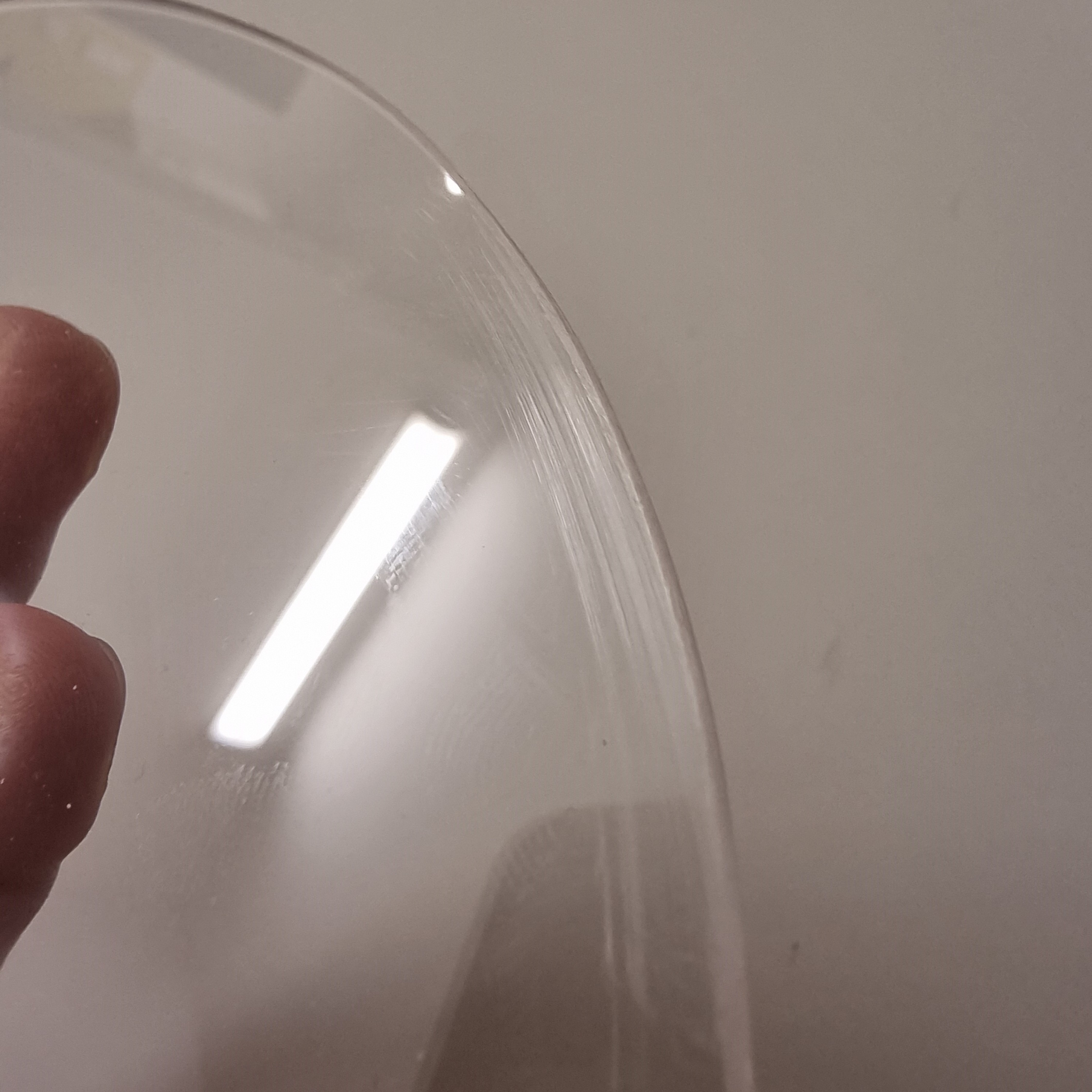
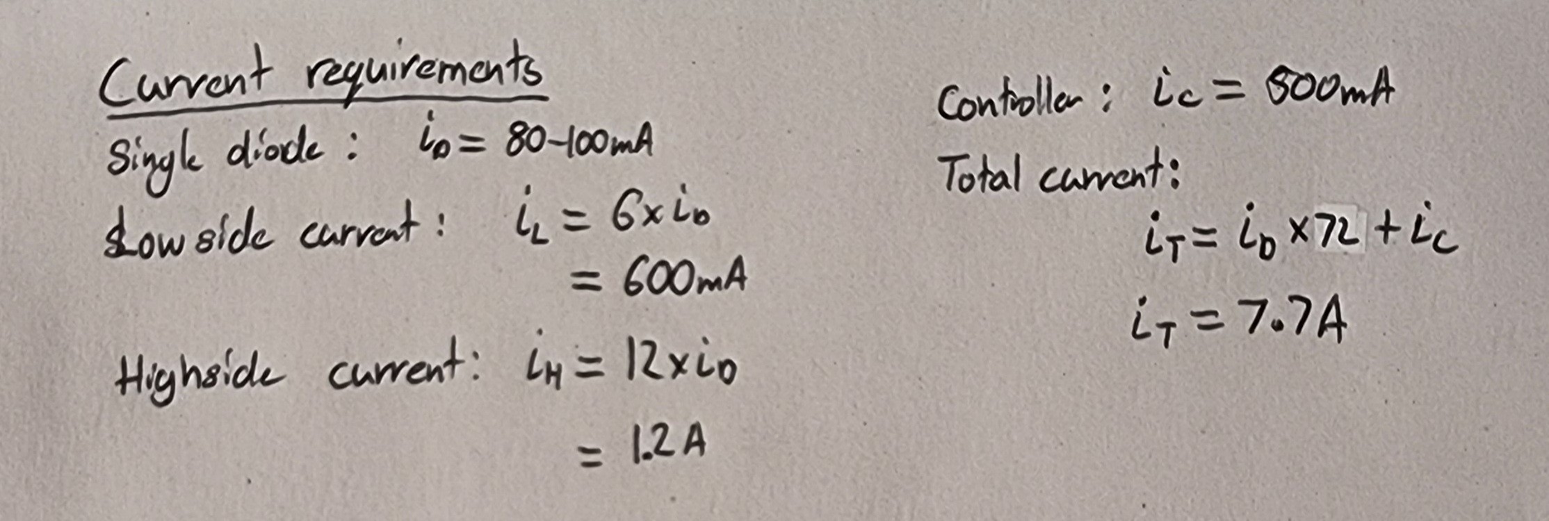
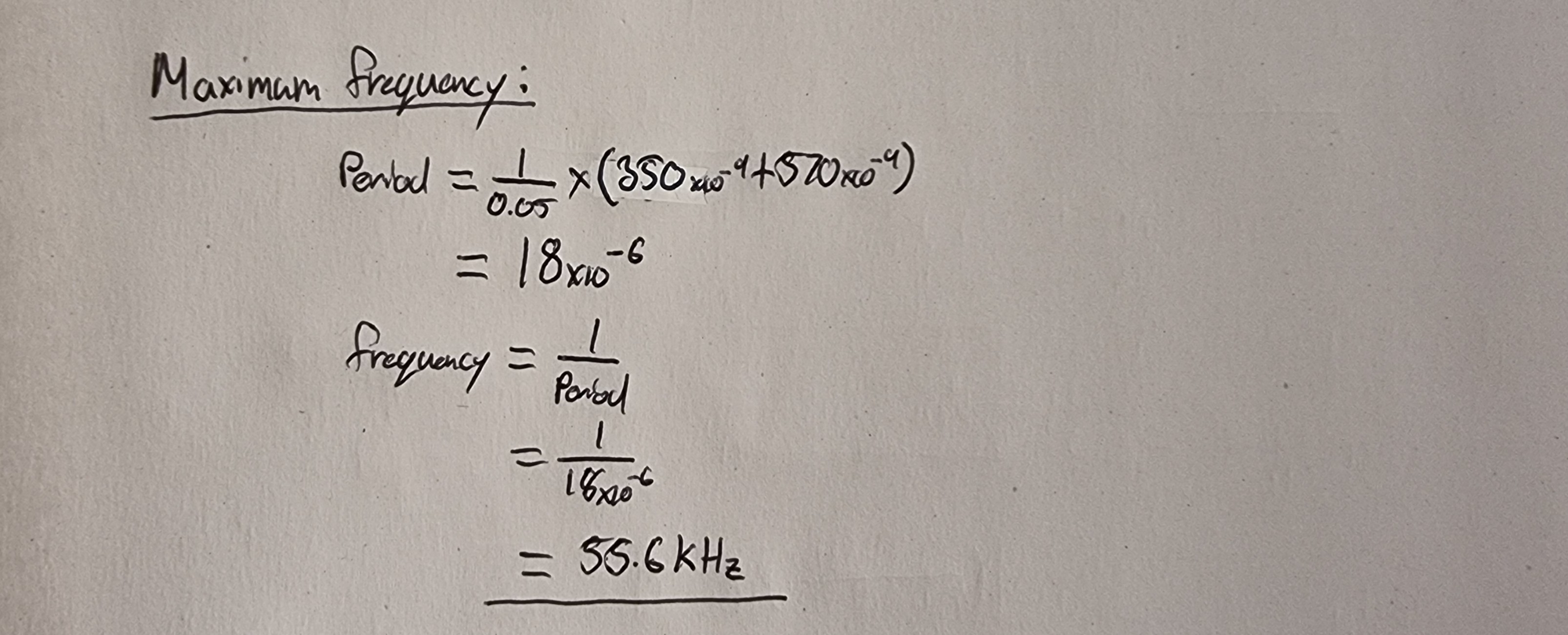
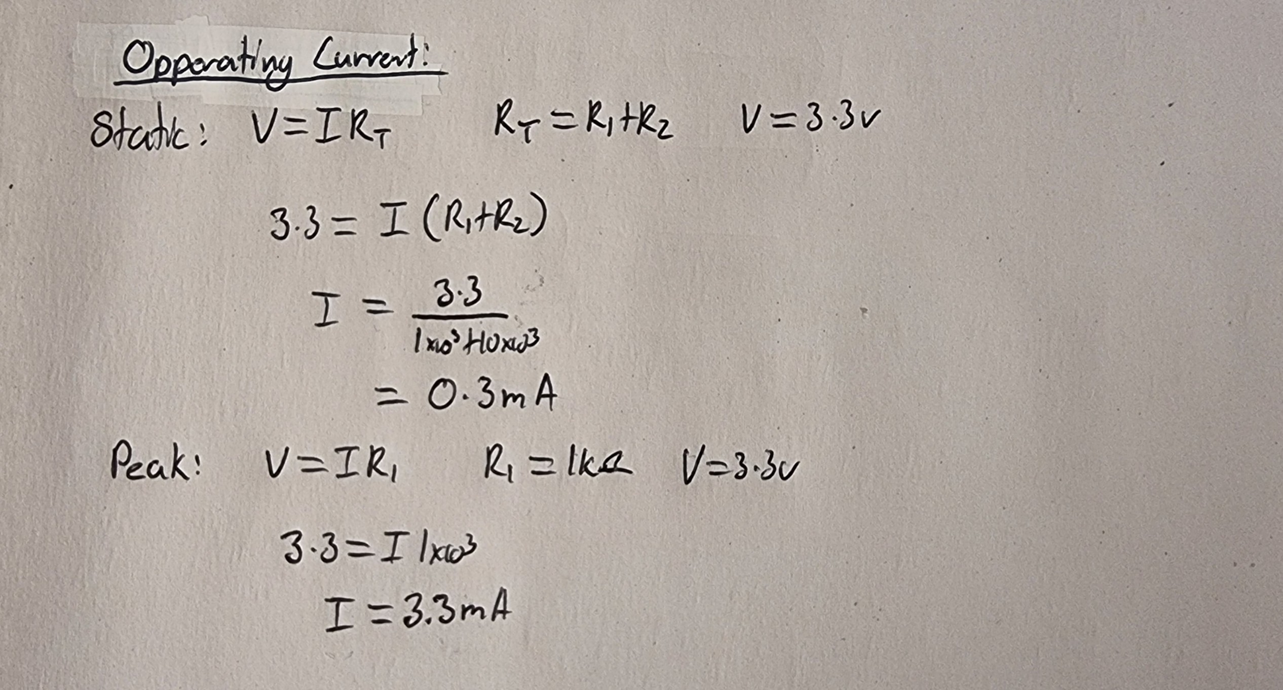
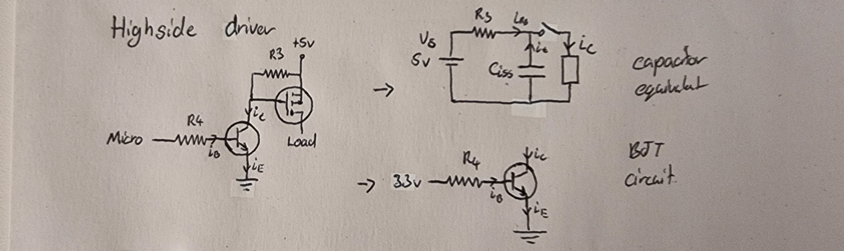
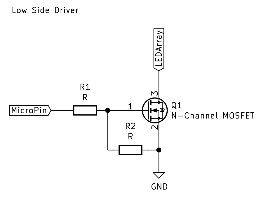
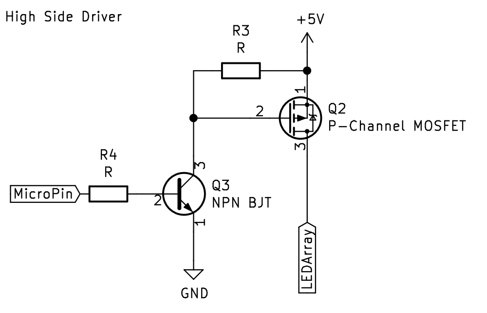
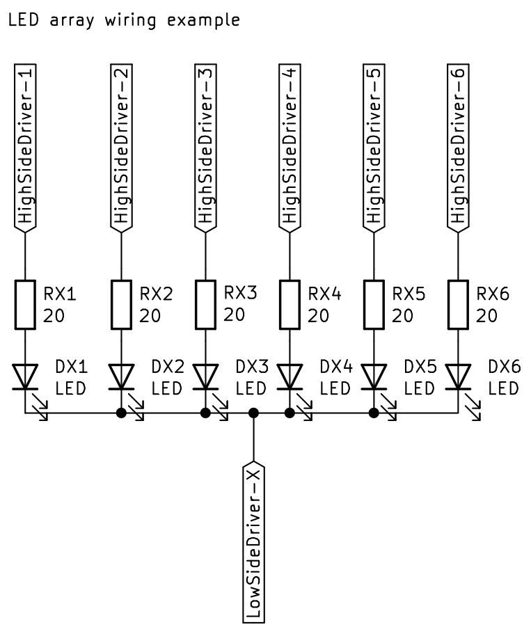
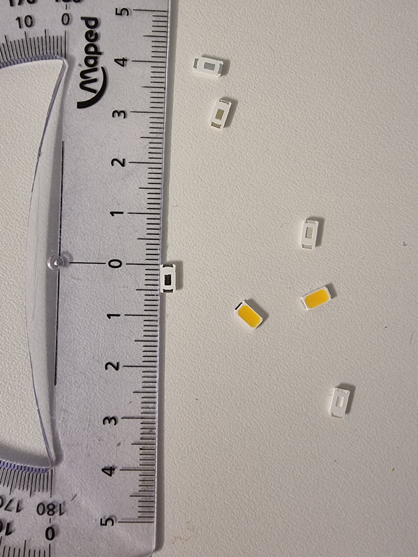
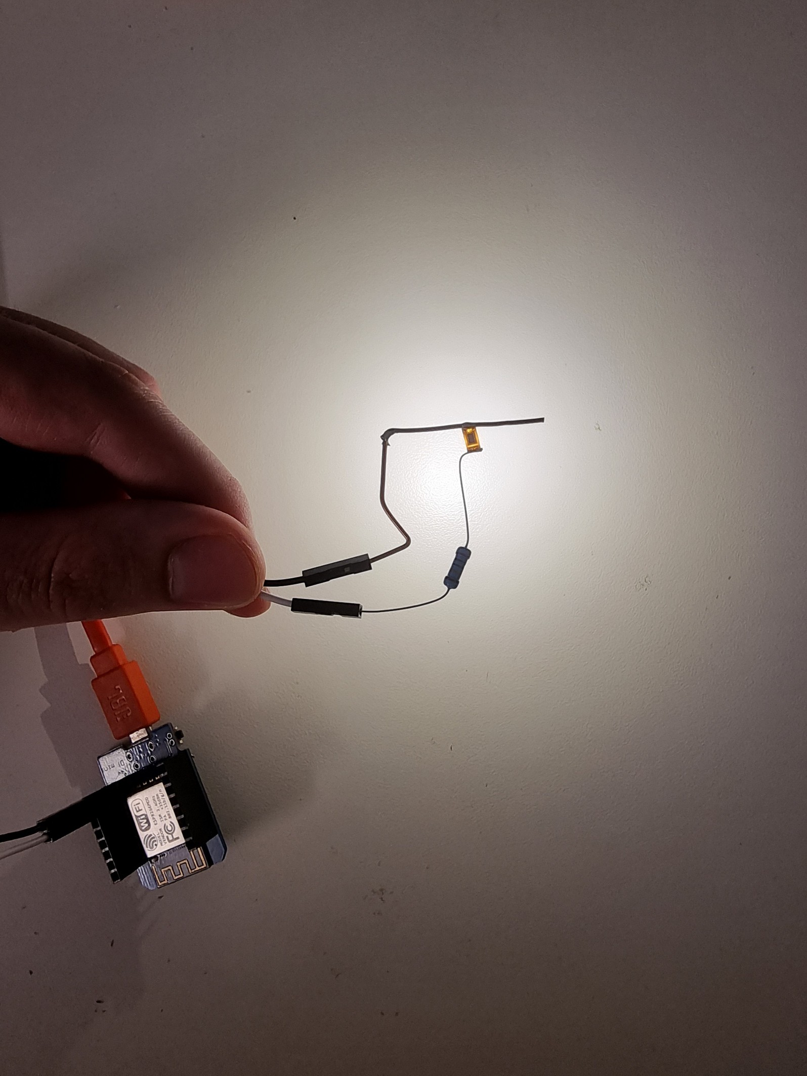
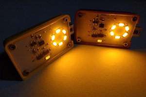
The basic concept is a free form circuit LED array sandwiched between two clear sheets of acrylic with an ESP32 controller. The array consists of two rings of LEDs, the outer ring containing 60 white SMD LEDs for displaying the minutes and the inner ring has 12 LEDs for displaying the hours. The LEDs are multiplexed using 12 low side rails and 6 high side rails. Everything is controlled using an ESP32 WROOM.  Other features not displayed in the concept sketch, but may be included later is a rotary encoder for interfacing with the clock, an LDR for light sensing and a speaker for alarms or notifications.

View all 19 components

  • Out goes the money

    Brennan P07/19/2021 at 19:57 0 comments

    After too much time thinking about the project and deliberating over each individual design choice it's time to bite the bullet and order some parts. The selection of these parts has come from what materials are available, calculations I performed in previous logs and the datasheets of the ESP32. I haven't quite finalised the circuits for the entire device yet, but I have given enough parts to compensate for this.

    The final parts list is as follows:

    Part Item Amount Source Price per packet Amount in packet Number of packets Total cost
    Front and back panels Acrylic 650cm^2 Bauhause 2 700cm^2 1 2
    Structure wire 1mm Enamelled copper wire 10m Amazon 12 11m 1 12
    Circuit wire 0.5mm Enamelled copper wire 5m Amazon 12 200g 1 12
    3.3V Voltage regulator MEZD71201A-F 1 Digikey 2.9 1 1 2.9
    Power supply SWI25-5-E-P5 1 Digikey 12.61 1 1 12.61
    Controller ESP32 Wroom 32E 1 Digikey 2.52 1 1 2.52
    N channel MOSFET FQU13N06LTU-WS 16 Digikey 0.496 1 16 7.936
    P channel MOSFET FQU8P10TU‎ 8 Digikey 0.558 1 8 4.464
    NPN BJT KSC1815YTA‎ 8 Digikey 1.73 1 8 13.84
    R0 20ohm resistor 80 Amazon 5.99 100 1 5.99
    R1+R3+R6 1kohm resistor 25 Digikey 0.0376 1 25 0.94
    R2+R5 10kohm resistor 24 Digikey 0.0376 1 24 0.9024
    R4 5.5ohm resistor 8 Digikey 0.038 1 8 0.304
    C1 0.1 uF 2 Digikey 0.19 1 2 0.38
    C2 22 uF 2 Digikey 0.3 1 2 0.6
    C3/C4 1 uF 4 Digikey 0.32 1 4 1.28
    LEDs 0.5W 5730 SMD LEDs 80 Digikey 9.59 100 1 9.59
    barrel jack 721A‎ 1 Digikey 3.13 1 1 3.13
    Encoder EN11-HSM1AF15‎ 1 Digikey 2.48 1 1 2.48
    Controller programmer ESP32-DEVKITS‎ 1 Digikey 8.41 1 1 8.41
    Total 104.2764

    Decisions yet to be discussed but present in the parts list are:

    • The selection of enamelled wire, which will make soldering more troublesome, but make the device significantly safer from shorts.
    • The addition of a rotary encoder with a push button along with associated debounce circuits.
    • Power smoothing and enable circuits found in the ESP32 datasheet.

    I already have the LED and 20-ohm resistors and with the purchase of some wire, it will give me more than enough soldering to do until the rest of the parts arrive from Digikey.

  • Its messy-o-clock

    Brennan P07/18/2021 at 20:56 0 comments

    After the maths, I decided to get my hand dirty and actually make something more than some marks on paper. This resulted in two circular panes of acrylic which will make up the front and the back of the clock. Since this is a "lockdown" project I haven't gone and used any fancy tools, just a couple of saws, markers, a compass, a clamp and some sandpaper.

    The acrylic sheet was bought at a local hardware store for 2 euros from the offcut bin. The acrylic was then cut up using a Ryoba saw, the only flat-bladed saw in my toolbox, and has the added bonus of a high number of teeth. When cutting acrylic sheets I recommend using a fine-toothed saw and clamping close to the cut to reduce the risk of cracking the acrylic.

    There was no real trick to putting the circle onto the acrylic, I just taped the marker to the compass. You could get fancy and try to protect the acrylic from the sharp point of the compass, but I figured that it would be hardly noticeable, which was the right assumption.

    With the circle drawn, it was finally time to get messy.

    I wouldn't recommend doing this in your bedroom like me, but without a workshop space what can you do. The final result was by no means a perfect circle, but it was observably good enough, and this was improved by sanding the edges round.

    When doing this I should have left the protective plastic on until the end, the lightest brush with the sandpaper left visible scratches on the acrylic. Maybe later they can be replaced with some nicer glass when I find some cheap and get the appropriate tools.

    But all in all, I'm happy with the result. For the next update, I'll have to order some parts, the last remaining decision for that is which wire to use, unshielded copper, or enamelled transformer wire.

  • Lets get the maths out of the way

    Brennan P07/04/2021 at 21:42 0 comments

    Now that the basic switching circuits for the LEDs have been devised some maths is needed to determine resistor values and total current draws so the appropriate parts can be ordered. I could probably select these based on a random guess and it wouldn't hurt, but it's nice to know the effect of resistors selection on the project.

    Current Requirements
    First off let's start with the current requirements for the driving circuits, a nice warm-up before we get into some more serious maths:

    Based on this, an operating voltage of 5V, and a control voltage of 3.3V the following devices were selected for the control circuits:

    I'm no expert so I don't know if these are the perfect parts for the job, but they should suit my purpose.

    You may have noticed the 7.7A draw when everything is turned on at the same time, this is expensive and not very feasible. Instead, I picked out the most reasonably priced power supply that can turn on a significant number of LEDs at once. Which managed to be the SWI25-5-E-P5 (https://www.digikey.de/product-detail/en/SWI25-5-E-P5/102-4200-ND). With an output of 4A max at 5V, it should be able to turn on 1/3 to 1/2 of the LEDs at any one time, which is more than enough considering their brightness.

    Low side driver

    Now let's move on to the low side driver circuit. I recently read that one of the downsides of using MOSFETs for driving circuits is their relatively high input capacitance, which can impact high-frequency switching, and since I want to drive these LEDs with a PWM signal some investigation is in order. So to start, let's begin with some pretty pictures.

    From the Micros point of view, the transistor is just a capacitive load. When this capacitive load reaches certain voltage levels it switches on or off based on the transistors gate threshold voltage. So for the circuits, we have replaced the transistor with a capacitor. The circuit can be simplified even more by replacing the source and resistors using Thevenin's equivalent circuit, reducing the calculations to a basic RC circuit, reducing the complexity of the maths. These equivalent values are as follows:

    Using these in a basic RC charging equation gives:

    And the same for the discharging equation:

    Using these two equations with two trial resistor values, the input capacitance of the MOSFET, switching voltages and solving for t can give us the total time required to switch the transistor on and off. Like so:

    Combining these two times, and allowing for 5% of the total period to be used for switching gives the following maximum PWM frequency:

    This frequency is well above the 10kHz maximum listed in the common PWM frequencies table for the ESP32 (https://www.espressif.com/sites/default/files/documentation/esp32_technical_reference_manual_en.pdf page 382), so in this regard the resistors are fine.

    But, it's not just enough to know the switching frequency, we also need to check that the current draw doesn't exceed the supply capacity of the IO pins. This calculation is done below:

    This current is within the limits of the ESP32 (https://www.espressif.com/sites/default/files/documentation/esp32_datasheet_en.pdf).

    So it looks like resistor values of R1 = 1k Ohm and R2 = 10k Ohm are suitable for this application. Finer tuning could be done to optimise the switching time or current limiting, but since this is my first attempt it gives me some leeway on either side.

    High side driver

    While the circuits for the high side driver has a few extra parts, it's actually a little easier since it can be broken into two simple circuits:

    The BJT is only used for discharging, so we will leave that for the end and start with the MOSFET charging...

    Read more »

  • In come the circuit diagrams

    Brennan P07/03/2021 at 20:17 0 comments

    As discussed in the description since we want individual control of the LEDs they need to be multiplexed. This is going to be performed with 12 low side driving and 6 high side driving circuits, resulting in 12 rings around the clock face each holding five "minute" LEDs and one "hour" LED. To reduce the power consumption and current load on the controller IO pins MOSFETs are the switching device of choice.

    First off, we will start with the low side driving circuit, nothing too special, resistor R1 is a current limiting resistor so the switching current doesn't burn out the microcontroller pins. R2 is a pull-down resistor so the gate isn't floating at startup, which could create some unexpected results. The calculations for these resistors are to be done later to balance current limiting effects and the switching frequency of the transistor.

    The high side driving circuit is a little more complex since the ESP32s operate at 3.3V and the LED driving voltage is 5V. For the MOSFET to be switched in such a situation a BJT transistor can be added to the circuit. This adds a little more complexity but has the added bonus that the switching logic turns on with a high signal. R3 in this circuit is a pull-up resistor which means the MOSFET is normally off, when the BJT is activated the gate of the MOSFET is pulled low and it switches on. The base current of the BJT will be quite low when active since it only needs to handle the current from the pull-up resistor and the capacitive storage of the MOSFET. This base current is controlled with R4. Same as the negative circuit the resistor values will be determined later through calculation.

    Just for reference, the final circuit diagram is an example array for one of the 12 low side loops with labels for connections to the driving circuits, LEDs and 20-ohm current limiting resistors.

    The next log will give resistor and current calculations so the BOM can be finalised and all the materials purchased.

  • Time for some bright LEDs

    Brennan P06/16/2021 at 21:22 0 comments

    The LED's have arrived after the impulse decision to finally go through with the project, they always end up being a lot smaller than I think they will, even knowing the dimensions beforehand. I did manage to solder one of the LED's to some copper wire, so the project is off to a good start. Mind you, I did melt one in my first attempt, lucky I have 20 or so spare.

    The LEDs are quite bright, I ended up using a 20-ohm resistor. With a 5V source, this gives a forward current around 100mA (80mA when checked with a multimeter). This is around 60% of the rated current for the LEDs, Even with this relatively low current, it's still going to require some more complex driving circuits than just some shift registers to light them all up.

View all 5 project logs

Enjoy this project?

Share

Discussions

Similar Projects

Does this project spark your interest?

Become a member to follow this project and never miss any updates