As discussed in the description since we want individual control of the LEDs they need to be multiplexed. This is going to be performed with 12 low side driving and 6 high side driving circuits, resulting in 12 rings around the clock face each holding five "minute" LEDs and one "hour" LED. To reduce the power consumption and current load on the controller IO pins MOSFETs are the switching device of choice.
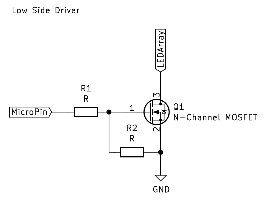
First off, we will start with the low side driving circuit, nothing too special, resistor R1 is a current limiting resistor so the switching current doesn't burn out the microcontroller pins. R2 is a pull-down resistor so the gate isn't floating at startup, which could create some unexpected results. The calculations for these resistors are to be done later to balance current limiting effects and the switching frequency of the transistor.
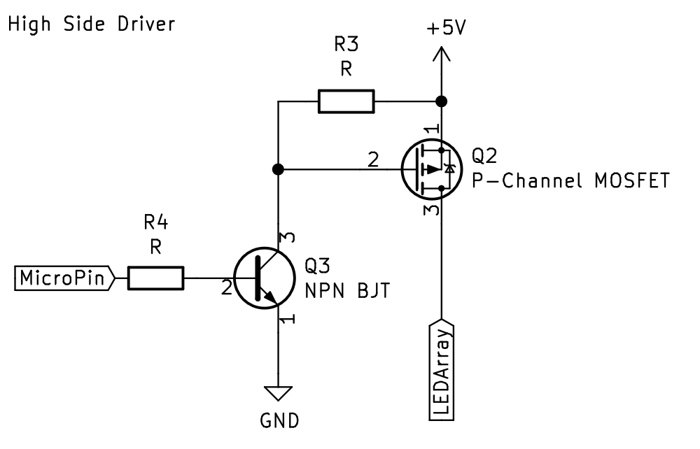
The high side driving circuit is a little more complex since the ESP32s operate at 3.3V and the LED driving voltage is 5V. For the MOSFET to be switched in such a situation a BJT transistor can be added to the circuit. This adds a little more complexity but has the added bonus that the switching logic turns on with a high signal. R3 in this circuit is a pull-up resistor which means the MOSFET is normally off, when the BJT is activated the gate of the MOSFET is pulled low and it switches on. The base current of the BJT will be quite low when active since it only needs to handle the current from the pull-up resistor and the capacitive storage of the MOSFET. This base current is controlled with R4. Same as the negative circuit the resistor values will be determined later through calculation.
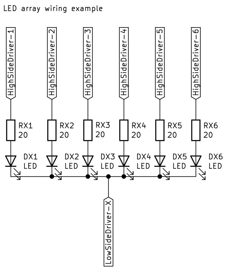
Just for reference, the final circuit diagram is an example array for one of the 12 low side loops with labels for connections to the driving circuits, LEDs and 20-ohm current limiting resistors.
The next log will give resistor and current calculations so the BOM can be finalised and all the materials purchased.
Discussions
Become a Hackaday.io Member
Create an account to leave a comment. Already have an account? Log In.