Making Work-From-Home Lighting Work-For-Me
A modular system to dynamically monitor and replicate outdoor lighting color temperature indoors while maintaining a stable light level.
A modular system to dynamically monitor and replicate outdoor lighting color temperature indoors while maintaining a stable light level.
To make the experience fit your profile, pick a username and tell us what interests you.
We found and based on your interests.
LightLevels_outdoor-indoor.pdfIlluminance guide for Instructors from NOAO, the national center for ground-based nighttime astronomy in the United States. Operated by the Association of Universities for Research in Astronomy (AURA). under cooperative agreement with the National Science Foundation.Adobe Portable Document Format - 455.32 kB - 06/18/2021 at 21:24 |
|
|
ColorSensors_AN000166_1-00.pdfApplication notes for Lux and CCT calculations using AMS color sensorsAdobe Portable Document Format - 304.91 kB - 06/18/2021 at 07:04 |
|
|
One of the neat ways I'll be physically extending this project is using SparkFun's QuiicBus Kit to drive the signals between the remote sensors and the controller over traditional ethernet wire. While both my sensors and the extenders are well documented, they're unfortunately not perfectly aligned in regards to their pin connections. In an ideal configuration I might directly connect the headers from one board to a female connector on another. Unfortunately, I'll instead be routing some jumpers because the key ground, voltage, SDA, and SCL pins aren't in an exactly matched order.
 | 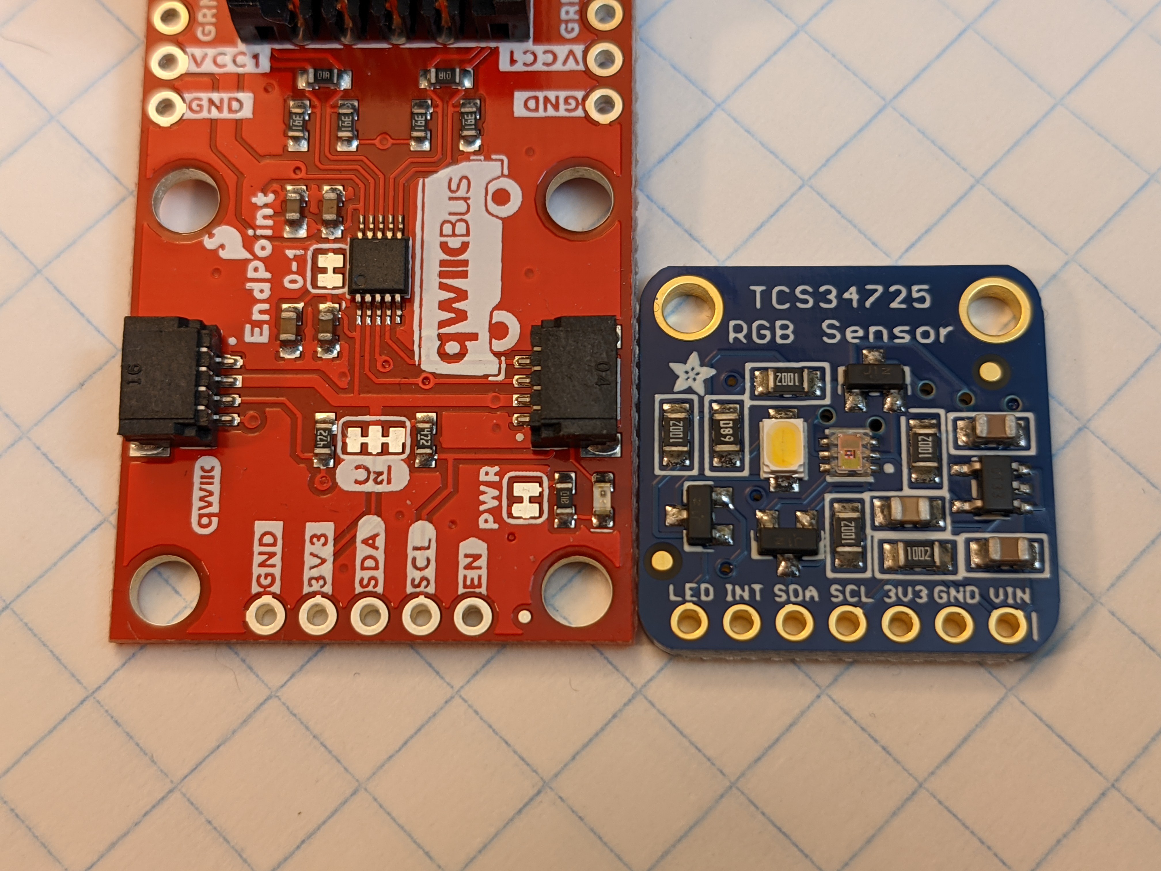 |
| The SparkFun QwiicBus MidPoint and Endpoint adapters alongside the Adafruit TCS34725 RGB sensor. Note the female RJ45 connector size for scale. | A close-up comparing the pin header labels of the QwiicBus system device and the Adafruit RGB sensor. |
I knew this going in (thanks to all the documentation) and honestly I'm more impressed when I see newer solutions that do work well together. I particularly applaud Adafruit for incorporating STEMMA QT connectors in some of their devices to provide connectivity with the SparkFun Qwiic system.
I'm sure others have found some solutions to this kind of problem ranging from elegant to terrifying, so I hoped to share my own experience in order to learn from those examples. Of course, a single custom PCB would bring everything together nicely. But even wiring the two boards together will still allow a remarkably small remote sensor that can get me started on my project in no time. On to collecting my data!
I've obtained some commodity LED light sources to use with a couple of lamps for the project. One of the design goals for this project is to create something that could disappear into the room, rather than the science fair aesthetic of my prior project. Although the picture below shows the lamps separated relatively far apart on top of a dresser, that is primarily to demonstrate the color temperature differences between the warm (2700K) and cool (6500K) sources. In operation, I'd want these two sources right next to each other. For the purposes of this project I expect to reconfigure these lamps as floor lamps standing next to each other.
I'd seen some desk lamp configurations, not unlike what you'd on the desk between a two-bed hotel space, which could have allowed for separately controlled sources. I'll likely investigate this later after I've proven out the solution with the relatively inexpensive lamps you see featured here. Overall I'll keep the control and lighting solutions separated. Part of the reason I want to separate the lamp outputs and controller system is that I can imagine a number of light source implementations, including floor and desk lamps, a troffer light with cool and warm sources for office spaces with suspended ceilings, or even indirect light sources like a tunable crown molding light source.
Overall, my goal will be to approach something like the solutions available from certain manufacturers, which bring the sources as close together as within a single lamp bulb. At the same time, a key goal for my project is to create a solution that could be scaled for a wider range of color temperatures and lighting levels where the costs are isolated to a simple control system rather than multiple smart lamps (which themselves often still demand a controller for full functionality).
In the meantime, I would want to highlight the significant color differences visible from the two sources I've positioned below. I'll go into more detail on future project logs, as I specifically plan to investigate some of my choices as they relate to target lighting levels vs. color temperature of the source. In the meantime, you can get some of the basics on color temperature from a log post (and the linked sources) I wrote during my last adventure into controlling the color temperature output of commodity lamps.
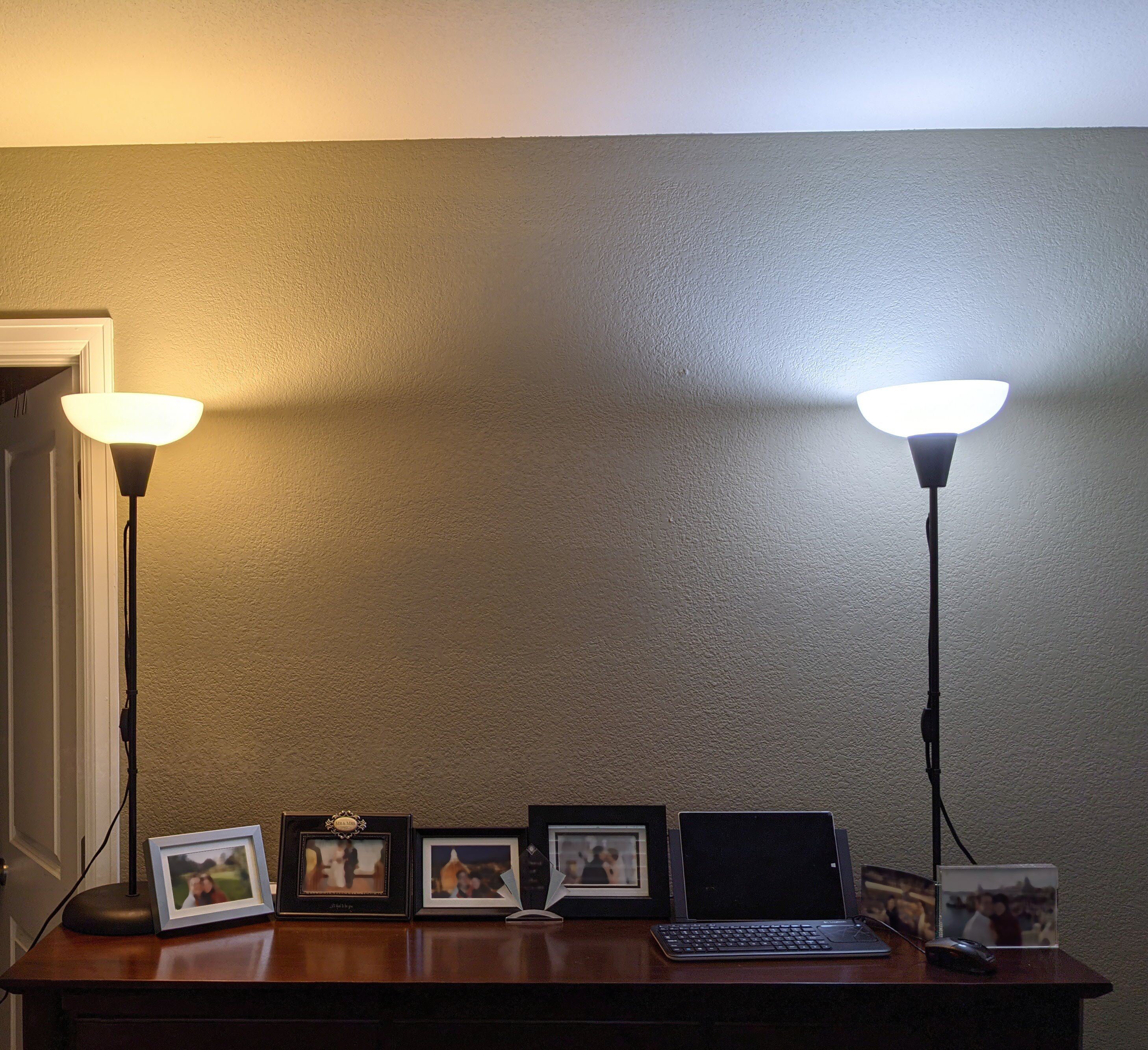 |
| Note the differences between the sources and the nearby green wall and white ceiling with the two distinct lighting color temperatures. |
In the first log entry I was able to get a sketch up and running to validate the expected functionality of my selected luminance/color temperature sensor. Connecting to my controller at that time involved what I'll term an excessive number of mini grabbers, but I was certainly excited to have gotten up and running quickly. Today marks another big preparation stage as I soldered the header pins onto the sensor board.
This is a big deal for me in part because this is actually the first time I've ever soldered. I've always enjoyed the use of breadboards or other modular systems, but I can now proudly check one more box in the kit. I'd love to tell you all about the amazing soldering station I acquired for this purpose, but the truth is I literally spent a few bucks to get the cheapest 30 Watt iron I could find to do the job. And most importantly, I and the circuit both seem to have survived the process intact.
One thing you can see from the circuit is that I chose to attach the headers to the side opposite of the sensors. This is to facilitate cleanly mounting the board toward the outside of a small project box. Otherwise, I was able to reconnect the appropriate I2C wires from my microcontroller (without the mini grabbers this time) and start my sketch right back where it left off.
Looking at the back, there is a difference you may note in the loop for the LED line relative to my first post. Rather than disabling the onboard LED by connecting it to ground, the LED control line is now looped back to the board's INT line. This enabled a software control of the LED using a single line of code to shut off the LED. The open/unused pin is for a 5V tolerant external power source. Instead I'm using a 3.3V line supplied from my microcontroller.
Immediately following this testing, I realized that I missed an opportunity to make use of the spare header jumpers I have in my PC parts bin. I'll likely continue using a header jumper for the LED control (as pictured below) - perhaps having an LED indicator line on the remote sensor might prove useful? My next step is to solder a header connector on the supporting board for this sensor to replace the jumper wires and make a compact remote sensor package. More on that soon!
My project has barely begun, but before I got too far I wanted to ensure that the sensors selected were up to the job. I am happy to report that initial tests are positive.
This entry is a bit of a prologue to more formal project updates. However, if you're seeking some insight into my source of inspiration for this year's project I'd simply point you to the project I constructed last year titled Lighting Color Control with Commodity Lamps. In that project I was able to validate that AC controlled commodity lamps were a simple, stable, accessible, and inexpensive way to produce a wide gamut of color temperatures. My project this year seeks to exploit capability as part of a system that uses commodity lamps regulated through a simple feedback control loop.
Although I had a lot of fun studying the spectrum of light output by various commodity LED lamps under AC control, I faced some difficulty in relying upon the illuminance and color temperature data returned by the sensors I selected. This year I have selected an Adafruit board built around the well documented ams TCS34725 color sensor to provide both light level (illuminance or lux) and color temperature data. I hooked up one of my sensors to a SparkFun RedBoard using some mini grabbers attached to Qwiic jumper leads. Disabling the onboard LED did require that I connect the LED via to ground, which explains the purpose of the loop you may notice being created with the white and orange mini grabbers.
Right away the default sketch was able to begin reporting meaningful illuminance and color temperature readings for my home office. I was able to switch on light sources, open and close windows, and notice expected results from the serial monitor (my artificial lighting was warm and would increase illuminance readings while lowering color temperature; opening the blinds significantly increased illuminance readings while also increasing the color temperature readings).
I was able to overwhelm the sensor's default sketch by walking outside, but a switch to the autoranging sketch proved more than capable of handling a full range of lighting conditions. I was able to take the sensor inside an unlit closet and then walk outside and see the gain and integration times adjust accordingly to produce reasonable lux and color temperature readings.
Inside the unlit closet illuminance measured less than 1 lux, lit only by the cool ambient light provided by my laptop screen
Gain:60x Time:614ms (0x0)
Raw R:13 G:57 B:18 C:90
IR:0 CRATIO:0.00 Sat:65535 Sat75:65535
CPL:118.84 Max lux:183.82
Compensated R:13 G:57 B:18 C:90
Lux:0.43 CT:6666.38K
Turning on the dim closet lights produced color temperature and illuminance readings in line with a dim (if sufficient) 2700K warm white light:
Gain:60x Time:153ms (0xC0)
Raw R:9759 G:5952 B:3164 C:19223
IR:0 CRATIO:0.00 Sat:65535 Sat75:65535
CPL:29.61 Max lux:737.69
Compensated R:9759 G:5952 B:3164 C:19223
Lux:198.37 CT:2626.25K
The home office with its mix of warm white lights and blinds-filtered daylight proved brighter and cooler in color temperature:
Gain:60x Time:153ms (0xC0)
Raw R:12161 G:12836 B:11319 C:34682
IR:817 CRATIO:0.02 Sat:65535 Sat75:65535
CPL:29.61 Max lux:737.69
Compensated R:11344 G:12019 B:10502 C:33865
Lux:300.51 CT:4918.21K
And walking outside produced a result reasonable for later afternoon/early evening in the 10k lux range but with color temperature around 5000K:
Gain:4x Time:153ms (0xC0)
Raw R:27643 G:25799 B:26190 C:58621
IR:0 CRATIO:0.00 Sat:65535 Sat75:65535
CPL:1.97 Max lux:11065.28
Compensated R:27643 G:25799 B:26190 C:58621
Lux:9082.24 CT:5000.73K
This is a promising start for what I hope will be a design that is modular and dynamic enough to work with a range of lighting choices while coming together in the kind of package I may use on a regular basis to enhance my home office lighting scheme. Thanks for joining me in this latest project journey!
Best,
Jon
P.S. -Note that the...
Read more »
Create an account to leave a comment. Already have an account? Log In.
Great questions, as first and foremost this question lets me know I need to work to get the project concept more clearly laid out!
There are three different lighting applications you've brought up: enhancing productivity, managing circadian rhythms, and light therapy. None of these are the initial focus of my project. However, I think a programmable light source capable of reproducing a broad range of light inputs could actually be part of a solution for all three applications!
As proposed my project takes local inputs and adjusts indoor lighting in real-time. However, if you abstracted the time factor (say, replicating the sunrise to midday cycle for a shift worker getting started at midnight) there's a way to use such a solution for the productivity application you mention. Similarly, altering light sources and/or integrating a bedtime schedule on top of the light input sensor routine might allow for support of a circadian reinforcement program. Abstracting time and location could even mean that you could replicate a summer day in sunny Phoenix for someone in the depths of winter in Sioux Falls (the light therapy application).
I think if you're fortunate enough, as I am, to be located in an area with plentiful sunlight year round (and a home office positioned to benefit from it) the idea of modifying artificial lighting to reduce the harsh distinction between artificial and natural sources has some value. At the same time, I also think that a system flexible enough to perform this function might have broad application for scenarios like those you've highlighted.
Let me know if I understood the applications you described correctly and thanks again for the post!
Become a member to follow this project and never miss any updates
 Jon
Jon
 Minimum Effective Dose
I hope you don't mind... I tried to read through the project... WHY would you do that, and I didn't find it.
Maybe I'm wrong but I think that replicating outside lighting conditions is NOT what we should do; why would you?
- When you wake up to start working you need bright white light (with nice blue content) to wake you up, not whatever gloomy light (or even dark) may be outside.
- Late evenings you want low, no-blue light to allow the body to prepare to go to sleep, not the bright skies one gets even at 10PM at summer solstice in the northern lands.
- When you come home in winter and it's dark outside, you want bright inside to cheer you up, or you'll get depressed.
Sure, it's interesting but I don't think it's useful. What am I missing?
Sorry :-(