 Jon
JonOne of the neat ways I'll be physically extending this project is using SparkFun's QuiicBus Kit to drive the signals between the remote sensors and the controller over traditional ethernet wire. While both my sensors and the extenders are well documented, they're unfortunately not perfectly aligned in regards to their pin connections. In an ideal configuration I might directly connect the headers from one board to a female connector on another. Unfortunately, I'll instead be routing some jumpers because the key ground, voltage, SDA, and SCL pins aren't in an exactly matched order.
 | 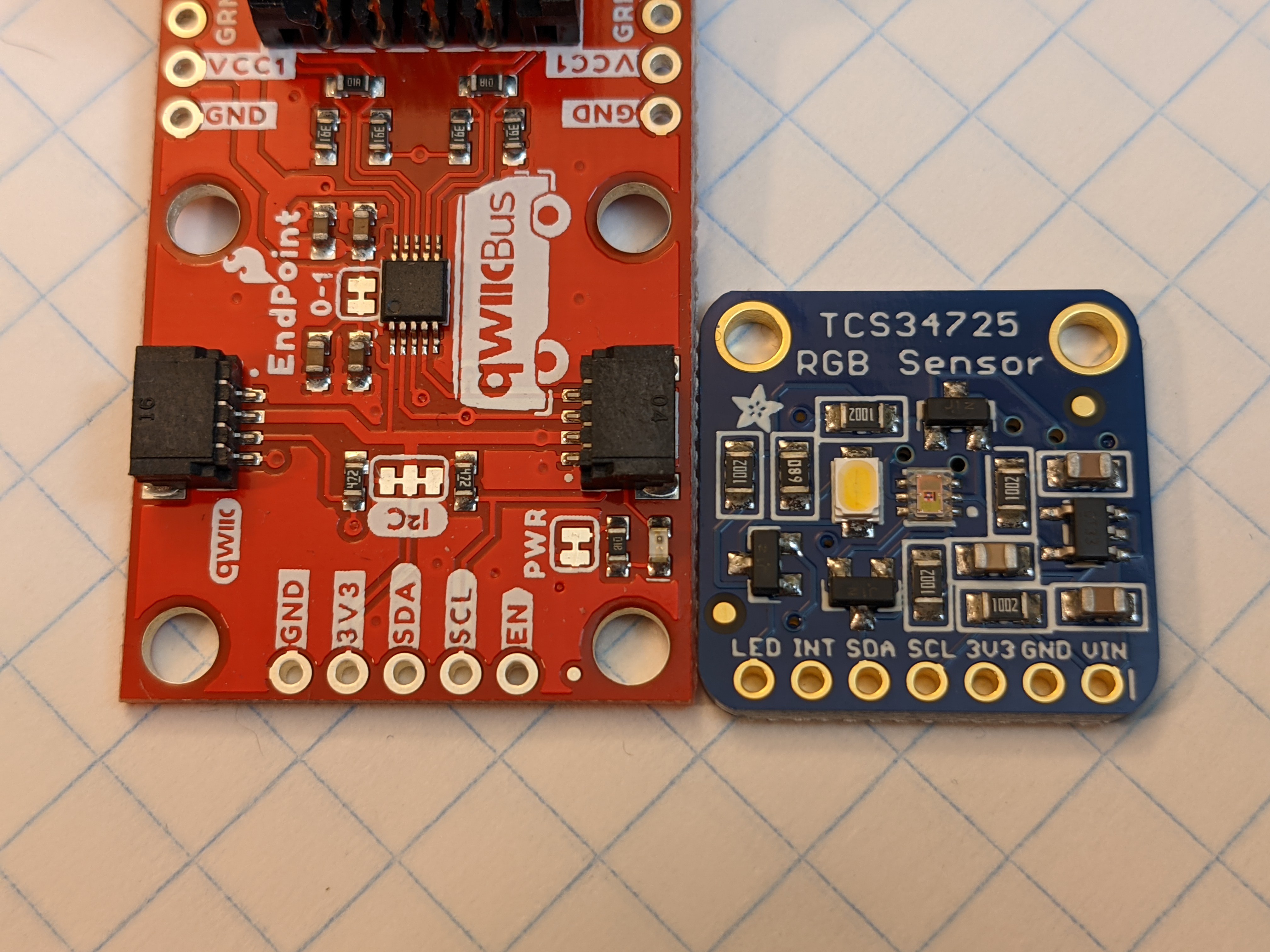 |
| The SparkFun QwiicBus MidPoint and Endpoint adapters alongside the Adafruit TCS34725 RGB sensor. Note the female RJ45 connector size for scale. | A close-up comparing the pin header labels of the QwiicBus system device and the Adafruit RGB sensor. |
I knew this going in (thanks to all the documentation) and honestly I'm more impressed when I see newer solutions that do work well together. I particularly applaud Adafruit for incorporating STEMMA QT connectors in some of their devices to provide connectivity with the SparkFun Qwiic system.
I'm sure others have found some solutions to this kind of problem ranging from elegant to terrifying, so I hoped to share my own experience in order to learn from those examples. Of course, a single custom PCB would bring everything together nicely. But even wiring the two boards together will still allow a remarkably small remote sensor that can get me started on my project in no time. On to collecting my data!
Discussions
Become a Hackaday.io Member
Create an account to leave a comment. Already have an account? Log In.