 Jon
JonIn the first log entry I was able to get a sketch up and running to validate the expected functionality of my selected luminance/color temperature sensor. Connecting to my controller at that time involved what I'll term an excessive number of mini grabbers, but I was certainly excited to have gotten up and running quickly. Today marks another big preparation stage as I soldered the header pins onto the sensor board.
This is a big deal for me in part because this is actually the first time I've ever soldered. I've always enjoyed the use of breadboards or other modular systems, but I can now proudly check one more box in the kit. I'd love to tell you all about the amazing soldering station I acquired for this purpose, but the truth is I literally spent a few bucks to get the cheapest 30 Watt iron I could find to do the job. And most importantly, I and the circuit both seem to have survived the process intact.
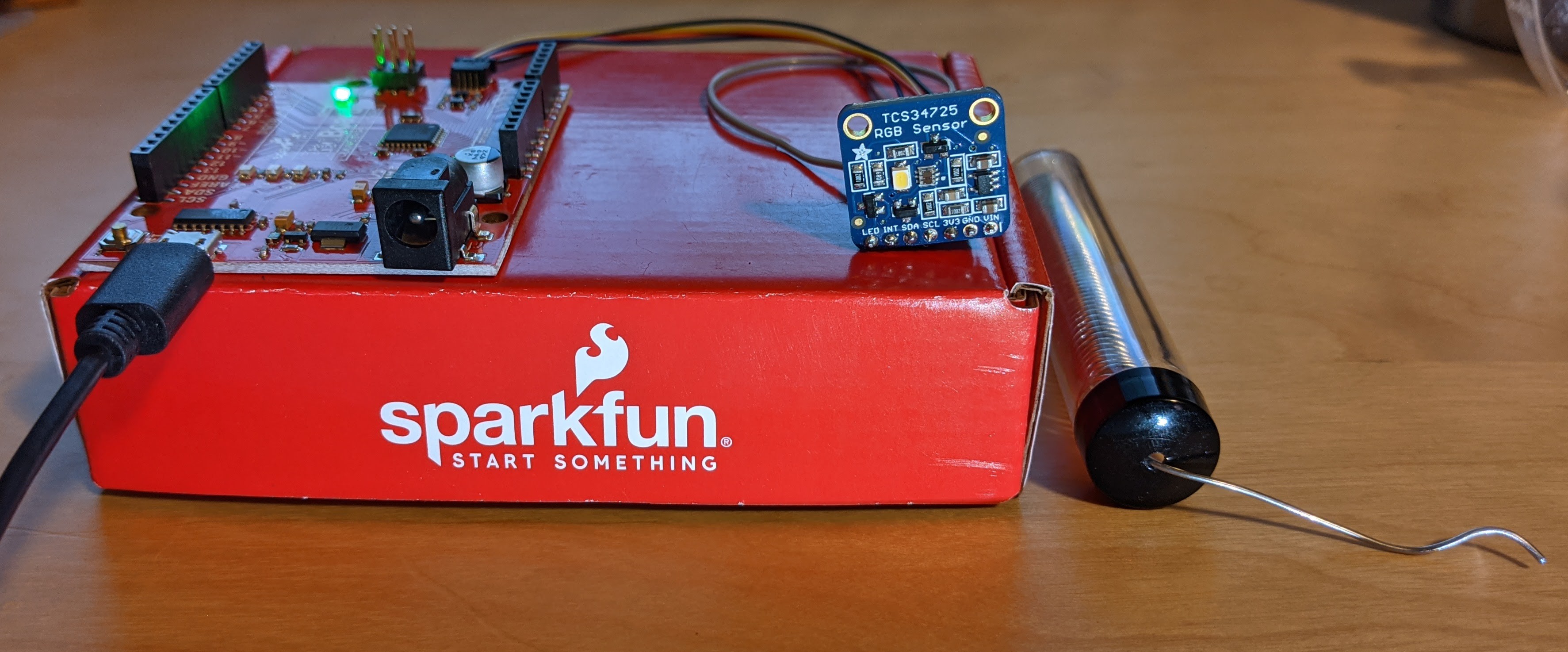
One thing you can see from the circuit is that I chose to attach the headers to the side opposite of the sensors. This is to facilitate cleanly mounting the board toward the outside of a small project box. Otherwise, I was able to reconnect the appropriate I2C wires from my microcontroller (without the mini grabbers this time) and start my sketch right back where it left off.
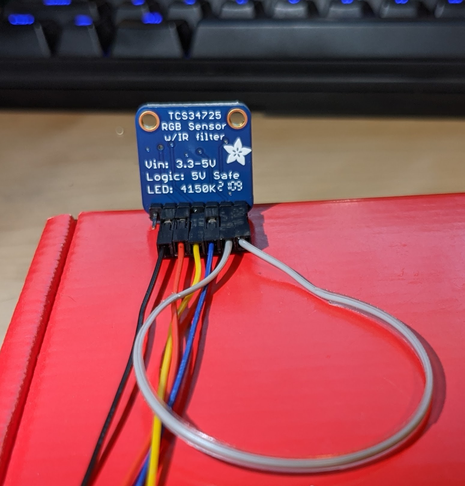
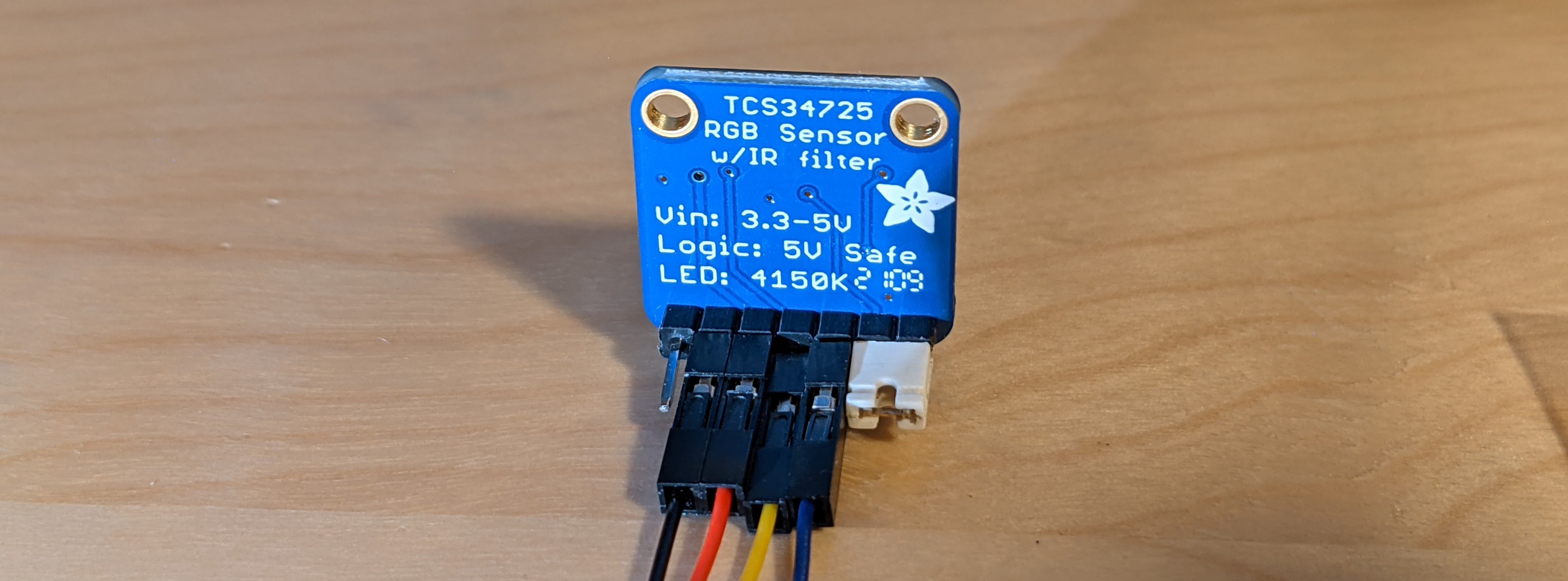
Looking at the back, there is a difference you may note in the loop for the LED line relative to my first post. Rather than disabling the onboard LED by connecting it to ground, the LED control line is now looped back to the board's INT line. This enabled a software control of the LED using a single line of code to shut off the LED. The open/unused pin is for a 5V tolerant external power source. Instead I'm using a 3.3V line supplied from my microcontroller.
Immediately following this testing, I realized that I missed an opportunity to make use of the spare header jumpers I have in my PC parts bin. I'll likely continue using a header jumper for the LED control (as pictured below) - perhaps having an LED indicator line on the remote sensor might prove useful? My next step is to solder a header connector on the supporting board for this sensor to replace the jumper wires and make a compact remote sensor package. More on that soon!
Discussions
Become a Hackaday.io Member
Create an account to leave a comment. Already have an account? Log In.