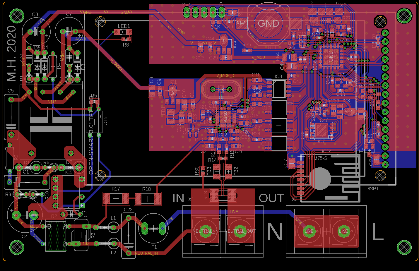
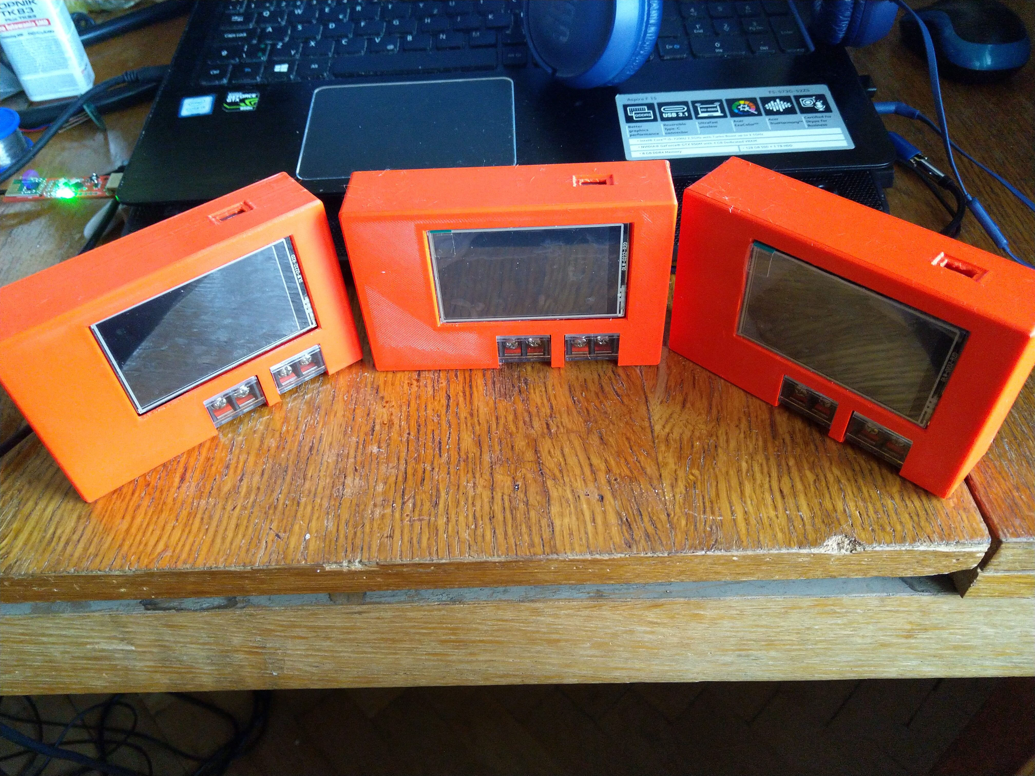
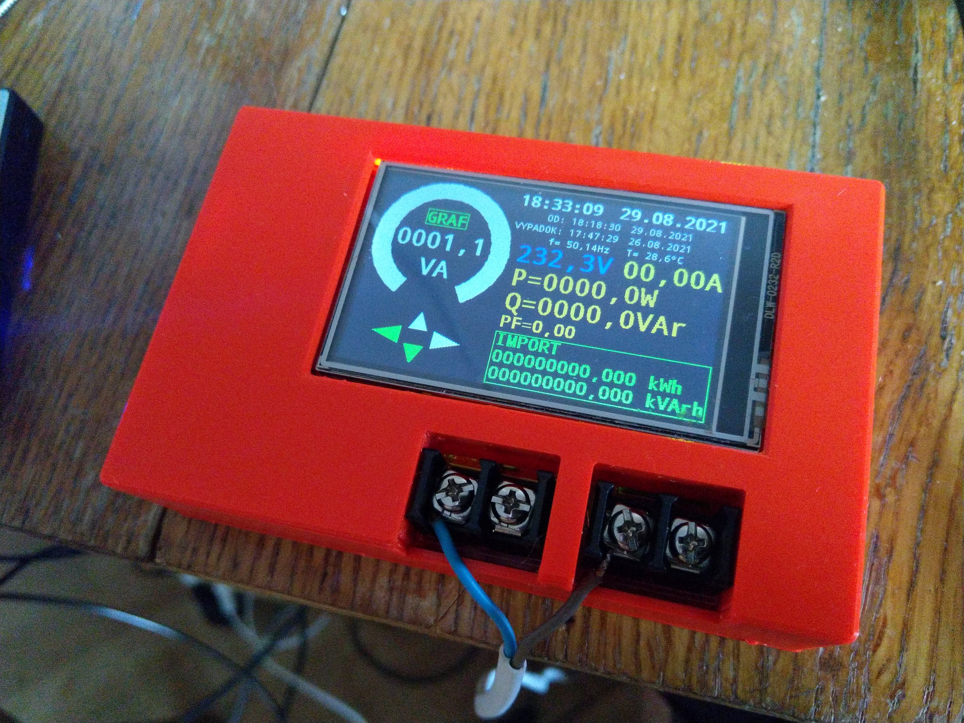
Measured values are displayed in numerical and graphical form. User can switch between screens by taping on left or right side of touchscreen. Additionally, display shows current time, power-up and last power cut timestamps. I chose RV-3028C as RTC and it works very well.
All measurements are logged into the SPI FLASH memory SST26WF080B which can store up to 16384 logs. (i used 1.8V "WF" version with level converter instead of 3.3V version because i got them very cheap). Default logging interval is 5 mins but it can be set in the range from 10s to 20min.
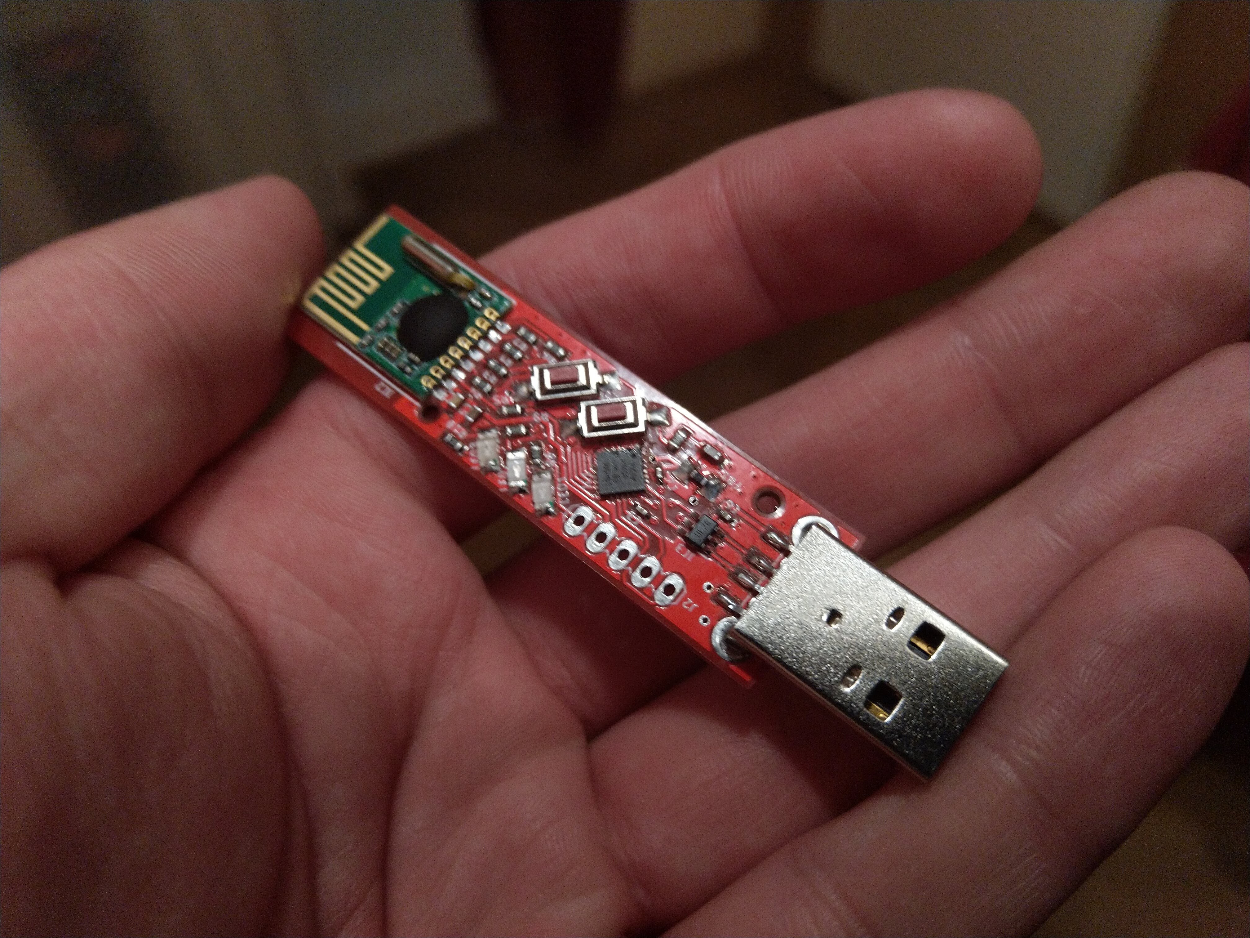
Reading data logs and changing settings and parameters is done by USB or remotely via RF transceiver RFM75 (USB dongle on PC side). RF control is not implemented yet, but I'm working on it.
Energy meter enumerates as CDC (virtual COM port) once it is connected to computer. It is possible to use any terminal software to read logs or set parameters.
Current FW version supports 7 commands:
--DT<hhmmssddmmyy> - set time and date
--READ<> - read current measurement
--ENER<> - read all energy accumulators (temporary and total)
--LOGS<> - read all logs from external FLASH memory
--LPER<ssss> - set the logging interval (in seconds)
--?LPER<> - read the logging interval
--DISP<n> - change screen (n: 0-primary display, 1-apparent power plot, 2-active power plot, 3-reactive power plot, 4-current plot, 5-voltage plot, 6-info screen)
This project is far from done and I want to add many other features (e.g. calibration). Hopefully i will update soon.

 Nikola Manolov
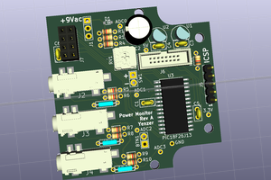
 Clara Hobbs