 SukkoPera
There are other projects like this one out there, but none of them is Open Source and none of them comes with both schematics and board. This is a big advantage, since anyone can modify the board and make new improved versions.
0%
0%
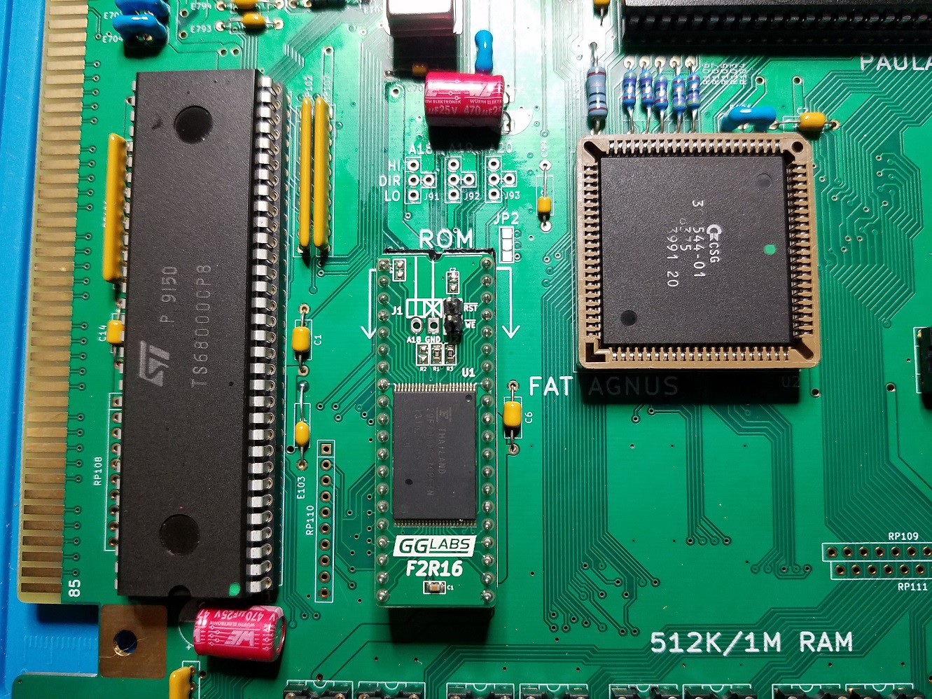
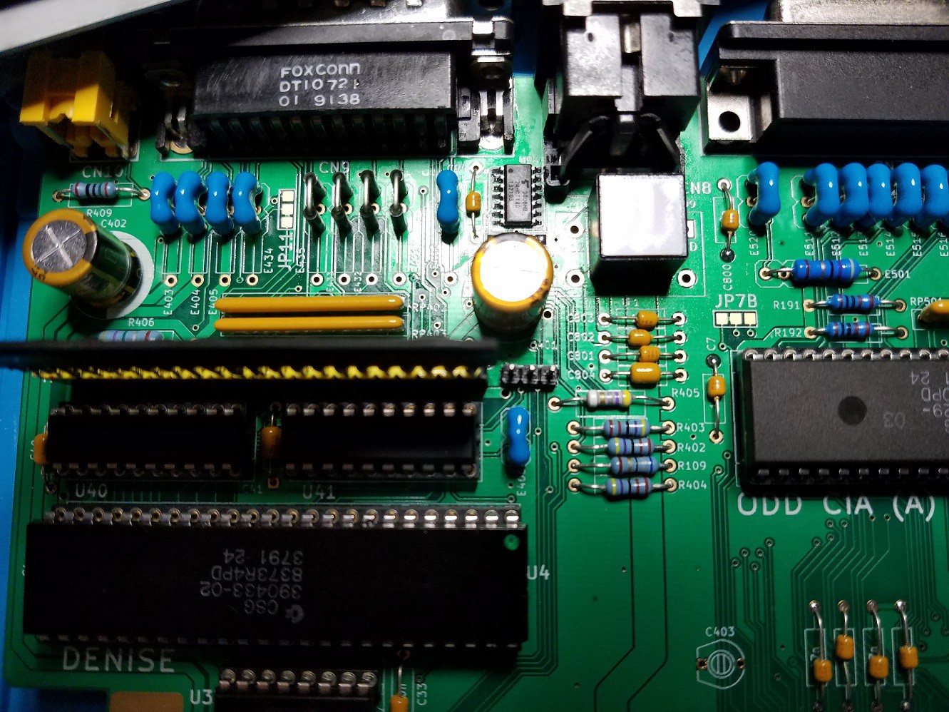
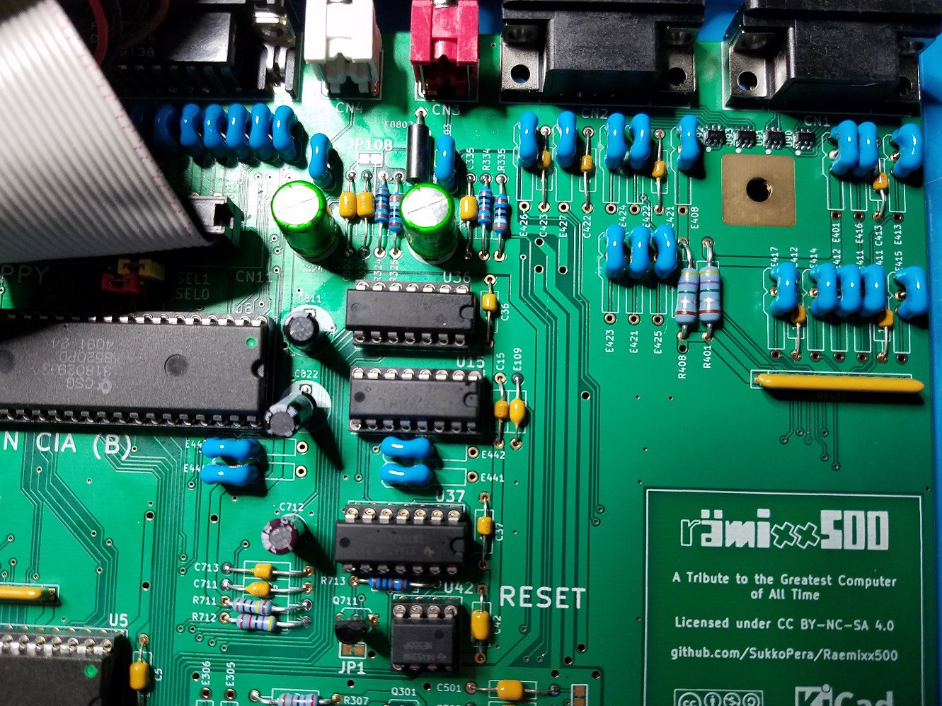
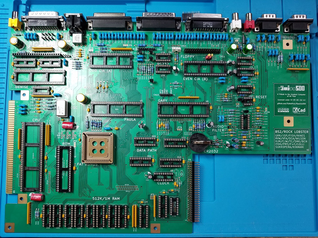
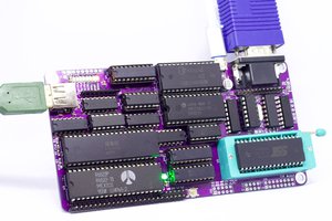
Rämixx500 - Amiga 500+ Mainboard
Open Hardware Remake of this Commodore Masterpiece
Become a Hackaday.io member
Already have an account? Log in.
Just one more thing
To make the experience fit your profile, pick a username and tell us what interests you.
Pick an awesome username
hackaday.io/
Your profile's URL: hackaday.io/username. Max 25 alphanumeric characters.
Pick a few interests
Projects that share your interests
People that share your interests


 Anders Nielsen
 Dave's Dev Lab
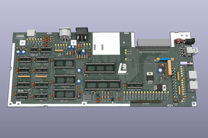
 Helen Leigh
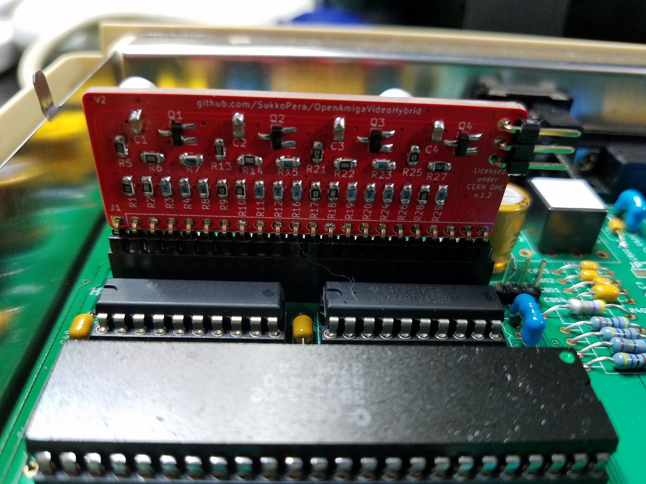
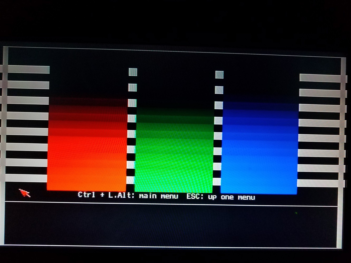
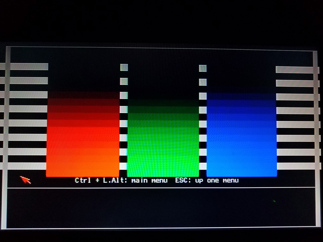
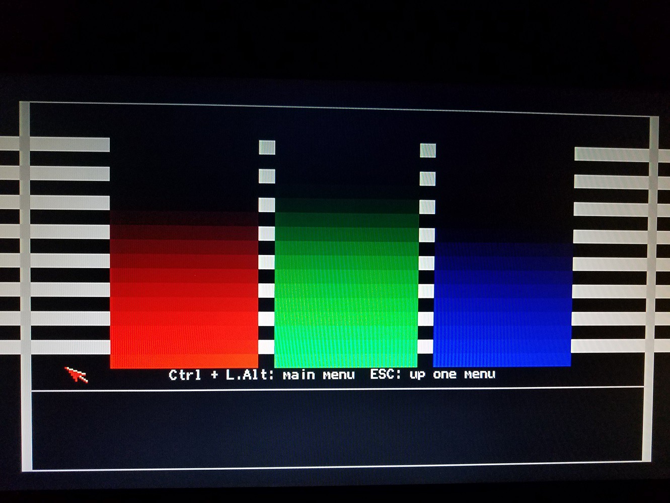
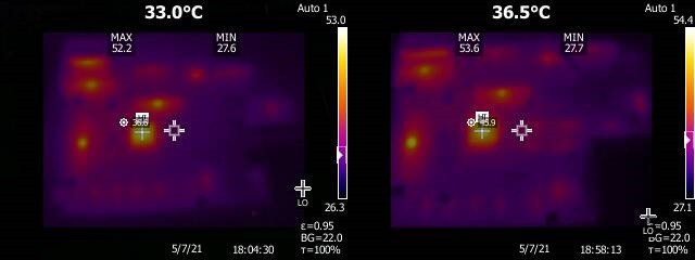
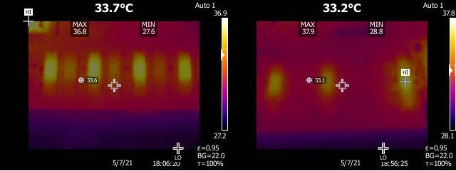
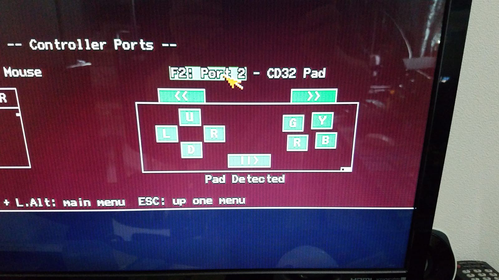
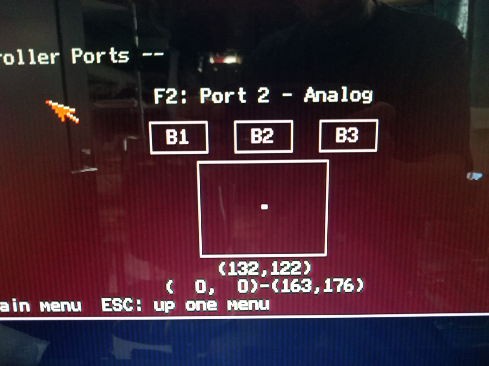
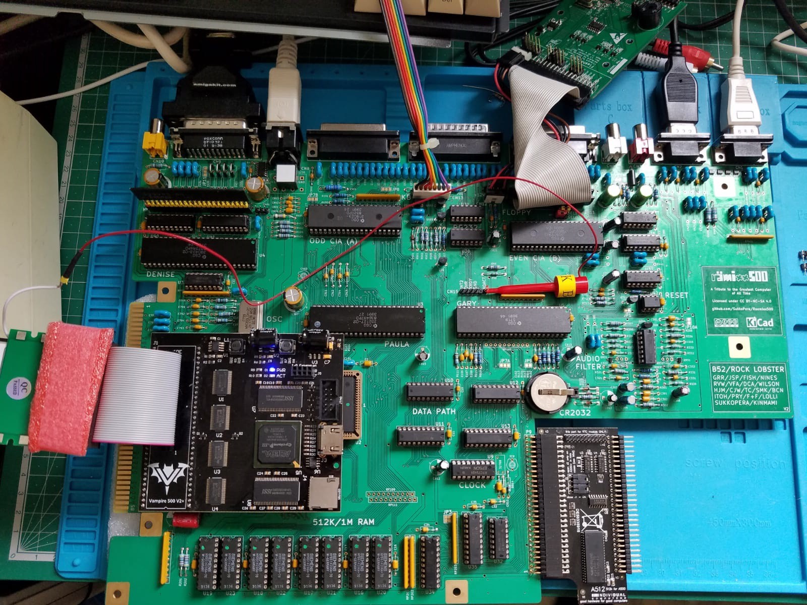
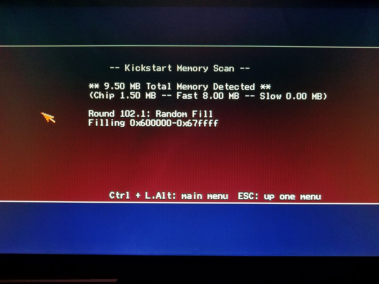
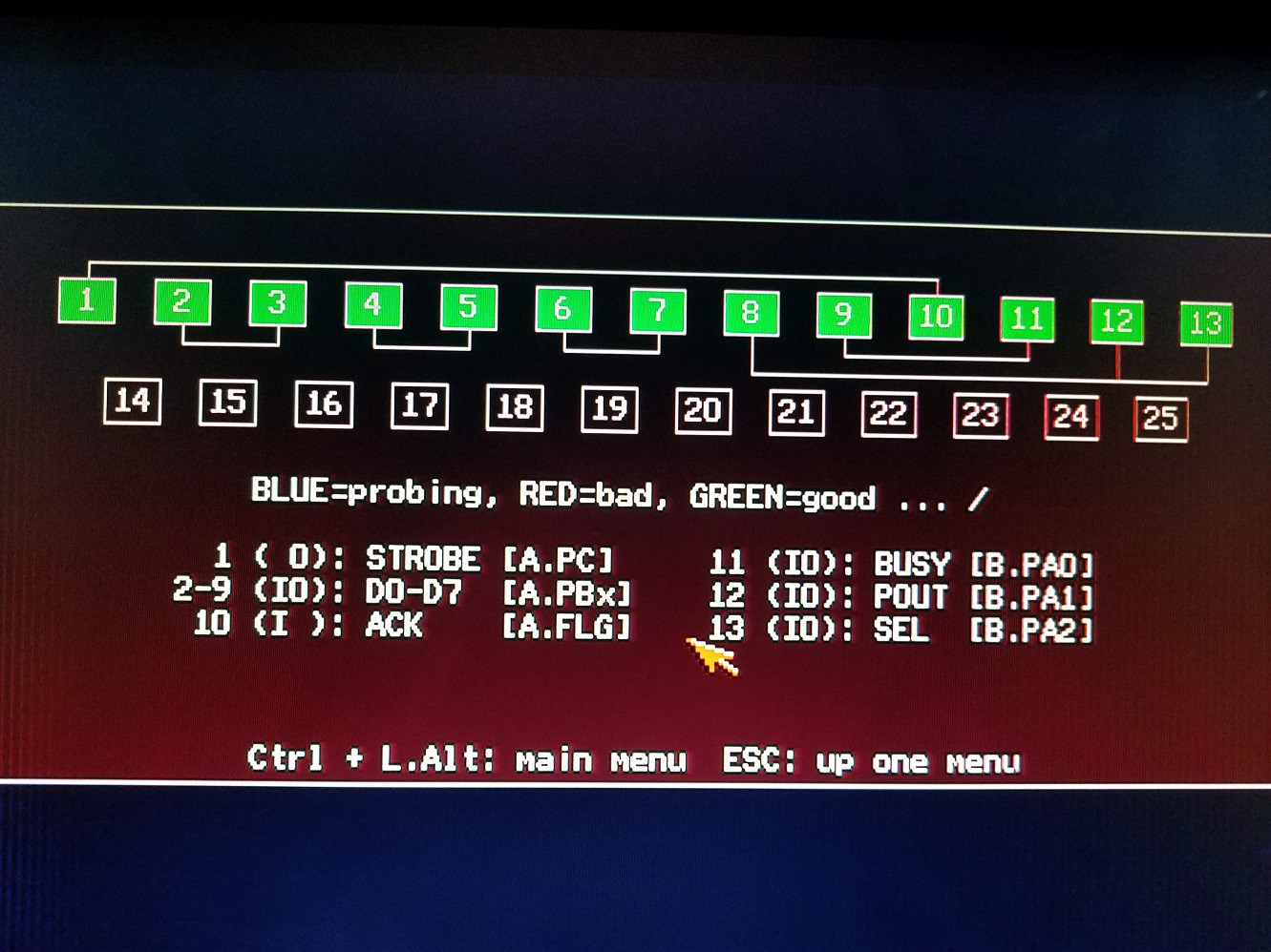
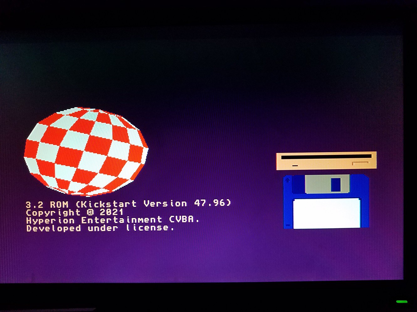
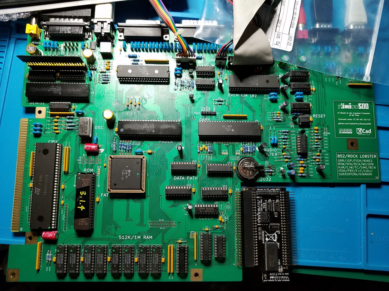
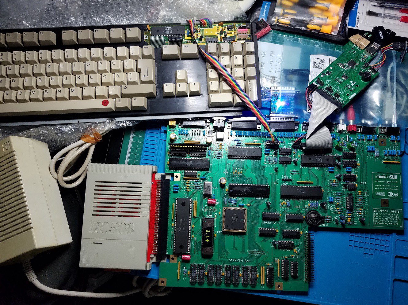
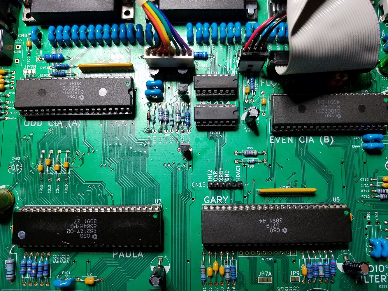
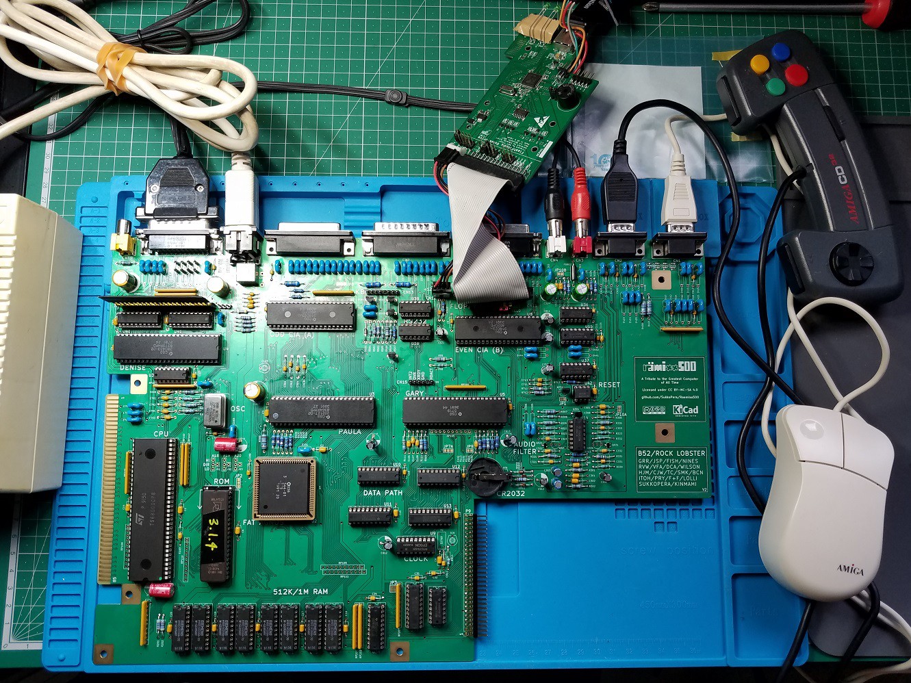
Just been building up a V2 board - finally after waiting months for components. Got a bit of an issue with it though. Anyone had any success or pointers before I get elbow deep in looking for errors