 Kevin Arne
Disassembling the Scale
If you're lucky, the commercial electronics you're looking to open up will be assembled with screws. This is especially true if space isn't a particular concern. Those screws often hide though, under things like rubber feet, screen decals, and even product decals. If you're unlucky, there will be adhesives or even ultrasonic welding of plastic parts.
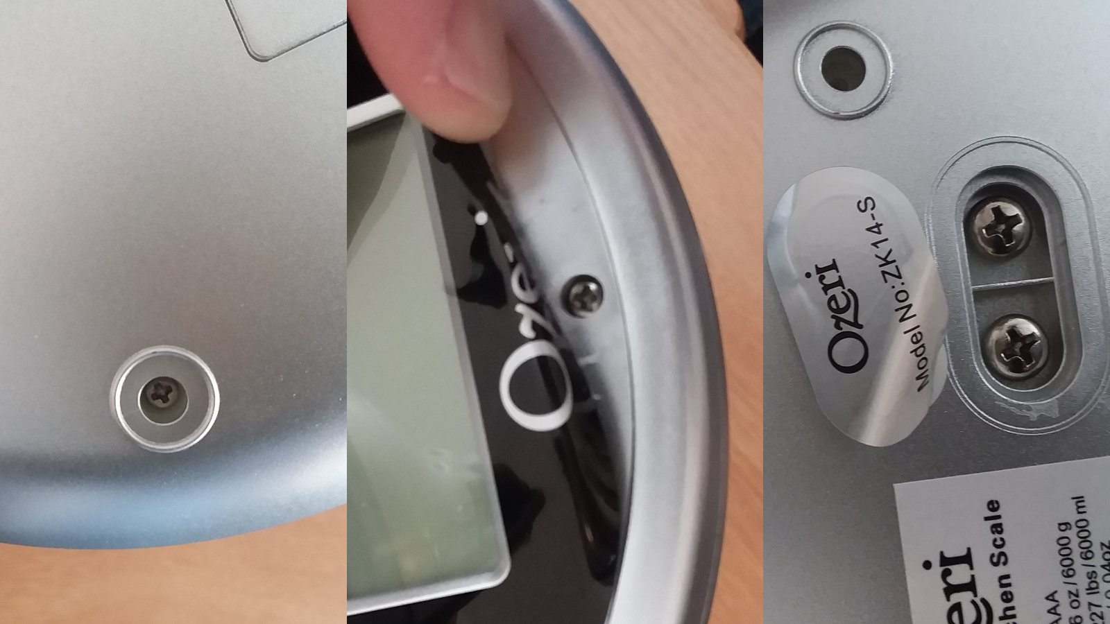
I was lucky. With the exception of a screw hidden under the faceplate, all of the screws were pretty easy to find and the whole thing came apart without the need to destroy anything.
Evaluating the Guts
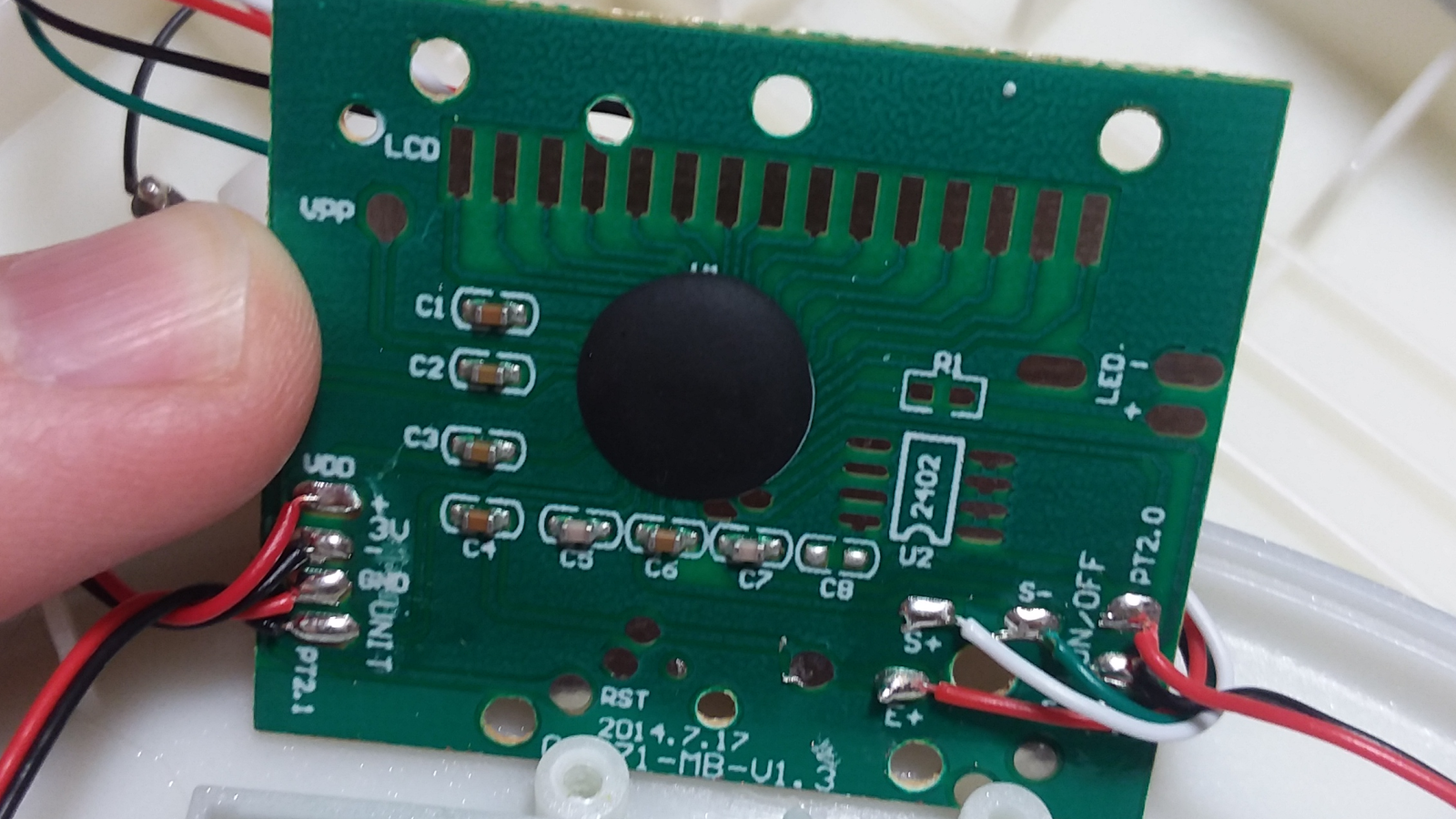
I was surprised to find no other resistors on the board, so the Wheatstone bridge is a full bridge (4 strain sensors). Upon some research, I discovered this is actually pretty standard for load cells. Sparkfun has a great article on getting started with load cells.
I was also surprised to see capacitors at every leg of the Wheatstone bridge. Perhaps these are for smoothing purposes?
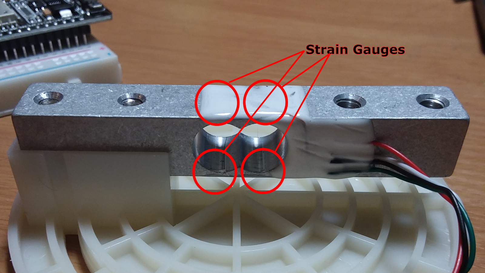
The cutout in the load cell is to ensure that deformation occurs there instead of distributed evenly throughout the bar. That cutout looks like someone drilled two separate holes. I assumed this was because of manufacturability, but was wrong. This geometry creates 4 weak points, allowing for the placement of 4 strain gauges: 2 in compression and 2 in tension.
Also no ADC or op-amp, unless they're under the epoxy blob, so either the microcontroller has a better ADC than the Nano, or the values are different enough that more resolution isn't needed. Looks like there's a spot for another IC, but it isn't populated.
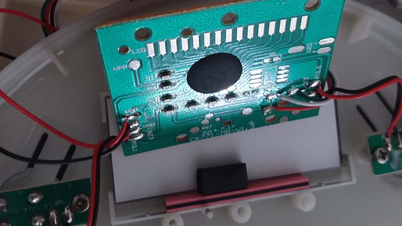
Surprisingly, there's no locking connector for the LCD, it just gets held on the PCB via the enclosure. Based on other teardowns of scales, this looks like it's pretty standard.
The individual strain gauge elements of this load cell appear to be 748 Ohms, very respectable, especially when compared to my gentleman's 3 Ohms.
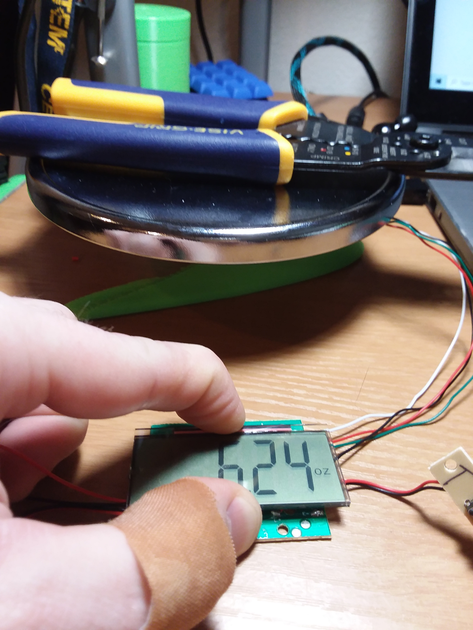
I ran the scale with no modifications (well, sprawled across my desk) and put a 6.24 oz weight on the scale (my wire strippers). My multimeter, which measures to 0.001 V, couldn't detect a change in voltage under load (1.273V at both junctions of the Wheatstone bridge). This means it can't be using a 10-bit ADC because those measure down to 0.003V with a 3V reference voltage.
What's Next?
Time to desolder the leads to the load cell and try using it with my ADS 1015 and a Nano. Based on the prices I've seen on load cells, this may be a better approach than rolling it all into one custom PCB.
I'm not sure there's a way for me to get a more sensitive strain gauge on a board than what I currently have. The only ways I know to make it more sensitive are to increase the resistance in the trace that makes up the strain gauge. To increase resistance, the trace needs to be longer or thinner. Thinner isn't possible because of the board manufacturer and longer increases the cost of the boards and takes up more space. The other thing I could do to try is getting an ADC with more than 12 bits of resolution, which will also be pricey.
Discussions
Become a Hackaday.io Member
Create an account to leave a comment. Already have an account? Log In.