 RossGK Tangibles
GPOD Log Begins
My GPOD project is a vehicle to explore the Hackaday and Tindie ecosystems. I picked this little prototype project to convert to a sellable item, and share the broad elements of the progress.
Only just noticed the existence of the "LOG" feature here, so I'll add a bit of info as I go along. This looks dangerously like a blog, and if the early 2000s showed us anything there are only two types of blogs - those that have been abandoned and those that are soon to be abandoned. I'll try to at least bring this to a conclusion with a finished device on Tindie.
The Story So Far
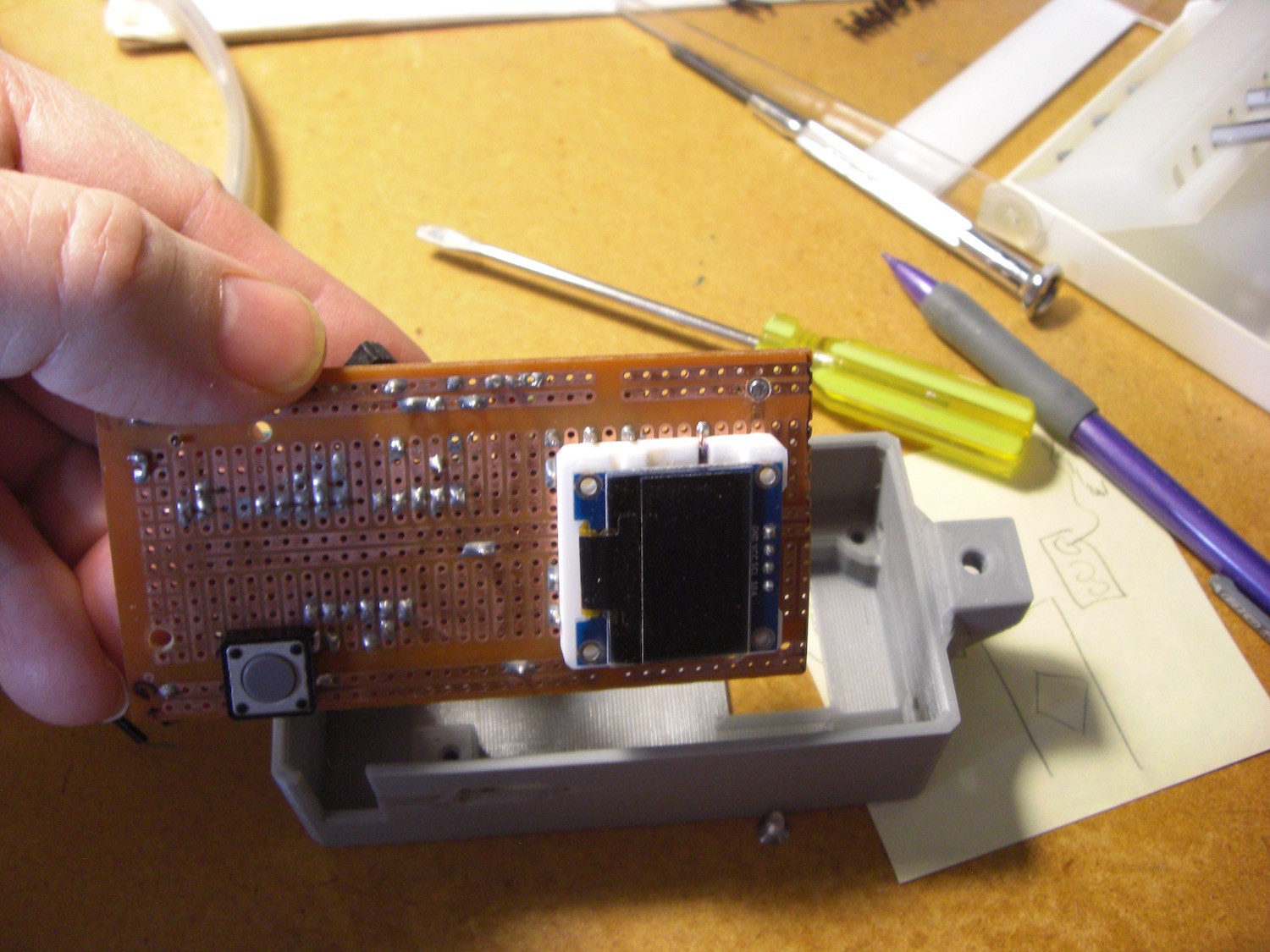
So far I've taken a circuit made on veroboard (prototyping circuit strip board) and turned it into a PCB. The circuit is essentially of the 'hat' variety, a board that connects to an Arduino board and provides interconnectivity. However, maybe in this case it's more of a 'shoe' as you don't plug this into the Arduino, the little Arduino Nano plugs into it.
My prototype was a simple grow light to get some plant seedlings growing during the dark months of the winter. It was quite successful, and I've been enjoying the literal fruits of the labour all summer, eating lots of tomatoes, cucumbers and kale.
The circuit simply provides power routing and connectivity for connecting the common serially programmable RGB LEDs to the Arduino. And I used the older 5V Nano Arduino because a) I had a few around not being used, and b) those SPLEDs tend to use 5V as well and I could keep the power distribution more simple.
I also have an OLED display screen to present a simple user interface, and a single button to control the UI.
PCB Evolution
After the first PCB I decided to make another version because there are always a few things you realize you could've done better after you have it in your hands. I also decided to add a few spots to put SPLEDs directly on the board for development purposes. Sometimes you want to write some code to control them, do various colours or patterns etc.
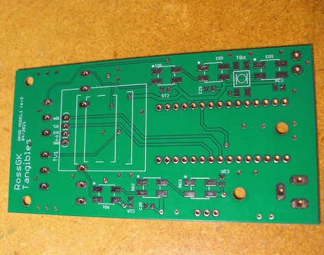
The board has four 'channels' and this allows mixing of different types of SPLEDs. Some are RGB, some are RGBW, and ther are a variety of different signalling methods. The code library I used to talk to them (Adafruit's) allows for all those conditions, so I also added a switch to the board to select between two of the most common approaches.
Discussions
Become a Hackaday.io Member
Create an account to leave a comment. Already have an account? Log In.