 Jianjia Ma
DeepPlankter
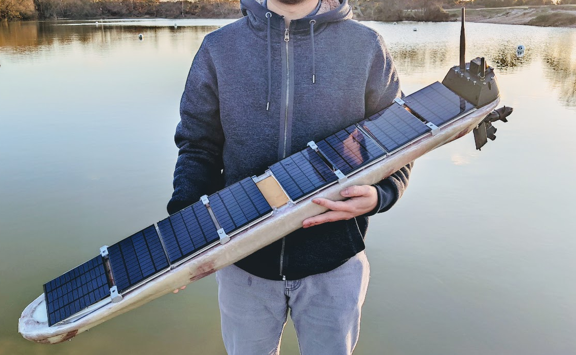
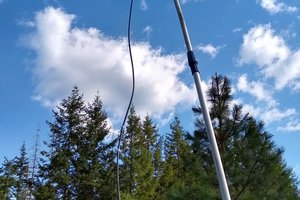
An autonomous wave and wind propelled drone boat.
It uses free energy in the surrounding environment to sail for a very long distance. It relies on in-air free-rotate wing and the underwater wings to provide propulsion and solar panels to power the onboard electronics.
See Github repo for the latest log: https://github.com/majianjia/DeepPlankter

-
The source code of navigation controller firmware will be hosted in its own repo (Not yet public)
-
Communication protocols and the remote control App/Website are NOT opensourced because of safety reasons.
Hardware
PCB file can be found in PCB folder.
The boat controller:
- Dimension: 80 x 100 mm
- MCU: STM32H7A3ZI, 280MHz, 1MB SRAM, 2MB Flash.
- NorFlash
- RTC
Sensors:
- IMU: BMI088
- e-compass: HMC5883L
- Environment sensor: BME280 (humidity, atmospheric pressure, temperature)
Power supplies:
- DC/DC LMR33640, 5.1V, 4A (max) x 3 controlled channels.
- DC/DC LMR33640, 3.3V, 4A (max) x 2 controlled channels.
- 2 battery connectors
- 2 charging connectors.
Extension IOs:
- 2 x 2P NTC (for each battery)
- 1 x 2P ADC
- 1 x 2P External LED (Flash light)
- 1 x 2P External Buzzer
- 3 x 6P UART (marked TELE1, TELE2, main GPS)
- 2 x 4P UART
- 2 x 8P SPI (MISO, MOSI, SCK, CS1, CS2, IO)
- 2 x 4P I2C (same PHY)
- 1 x 4P FDCAN
- 1 x USBD
- 1 x 24P FPC DCMI camera interface (for OV2640)
- 1 x 8P FPC and 2x4 rows debugging port (SWD + UART)
- 1 x SDCard slot (SDIO)
Battery, solar panels and MPPT chargers
- Battery 1: 18650 1500mAh 2S 9P
- Battery 2: 18650 1500mAh 2S 9P
- Panel set 1: 12V 160mA 4P
- Panel set 2: 12V 160mA 4P
- MPPT charger: BQ24650 model x 2
- 2S over current protector and balance x 2
- NTC x 2
The power of the whole boat is purely supplied by solar panels. We need to ensure the main controller never run out of power. The power distribution is managed by the main controller board. 8 panels are grouped into 2 set with 4 panels in each set. Each set of panels charge one battery through an independent MPPT charger and is balanced by an independent protect board. The power from the 2 batteries finally merges to a power rail through 2 ideal diode circuits. Then the power can be distributed by the main controller board.
The voltage and current of each charging circuit and battery are monitored.
Energy estimation
Each panel is rated 12V@160mA. In a sunny April day noontime, the maximum current measured is 10.5V@120mA when laying flat (simulate the angle on the boat).
So the peak power is around 1.25W for each panel. 8 of them can generate 10W.
But there are efficiency drops due to DC/DC converter and the battery charging efficiency. We assume it is around 0.8, so the peak power to charge the battery is 8W.
The peak power multiple by the term, "peak sun hours", is the energy that is generated per day. For example, per this blog, in the UK summertime, the peak sum hour is 5 hours, while in the winter, the number drops to 0.5 hours, so the power generated per day is around 40wh to 4wh.
The average daily solar insolation in units of kWh/m2 per day is sometimes referred to as "peak sun hours". The term "peak sun hours" refers to the solar insolation which a particular location would receive if the sun were shining at its maximum value for a certain number of hours.
Sailing during the winter is definitely a nightmare for the boat no matter how big the battery is, it will be drained out very soon if we don't cut off the power to every module or put them into sleep mode.
We have 2 battery sets, each can store around 100Wh. It needs 5 sunny days to fully charge.
Both batteries together can supply a 1W consumption (3.3V 300mA) for a good week until the next sunny day. Or 0.2W (3.3V 60mA)for a month.
Contact
Jianjia Ma
majianjia(-at-)live.com


 PacificBots
 Matej Gurnak
 Dan Maloney