 Enki
EnkiTable of Contents
- 1. Overview
- 2. The charger hardware
- 3. The LCD and its interface
- 4. The SPI sniffer
- 5. The sidekick board
- 6. The sidekick sensor board
- 7. Future developments
- 8. Addendum
1 Overview
The Liitokala Engineer Lii-500 is a universal chemistry 4-cell smart charger manufactured by the well-known Liitokala brand. It is very popular with people building battery packs out of second life 18650 Lithium-Ion cells because of its reasonable price and discharge capacity testing feature (NOR TEST mode). I own a number of those chargers and I use them as part of my cell assessment workflow. What I have found however is that entering cell capacity values reported by the charger manually into a computer is both a bit tedious as well as prone to mistakes. Therefore I have made attempts at automating the process by modding the charger.
The overall idea was to reverse-engineer the charging and discharging circuits to the point that I would flash my own firmware into the microcontroller inside giving me the ability to automate the charging/discharging process and read out the measured cell parameters.
Please take note, that all of the content here relates to the Lii-500 charger not the Lii-500S charger. The Lii-500S is a newer version of the Lii-500, the outward appearance is very similar but the internal board microcontroller and LCD screen are entirely different.
2 The charger hardware
The popularity of the Lii-500 charger means, that there are multiple modifications and hacks already published, a quick search on youtube reveals a number of videos showcasing the internals or multiple hacks that are possible with this charger. In particular:
- Disassembly video, adding a connector to test pouch cells
- A different disassembly video
- Review and disassembly
- Disasembly and button replacement
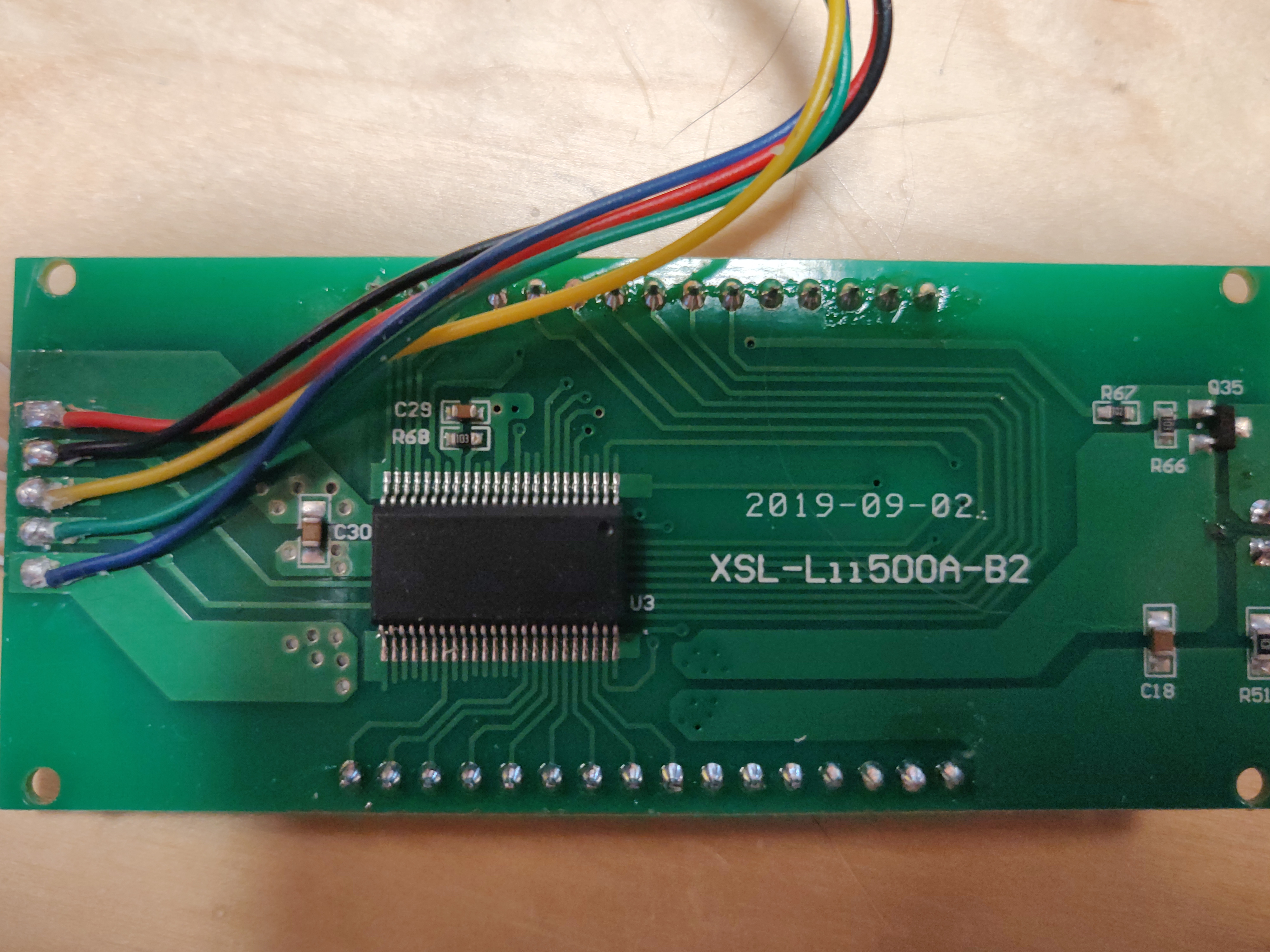
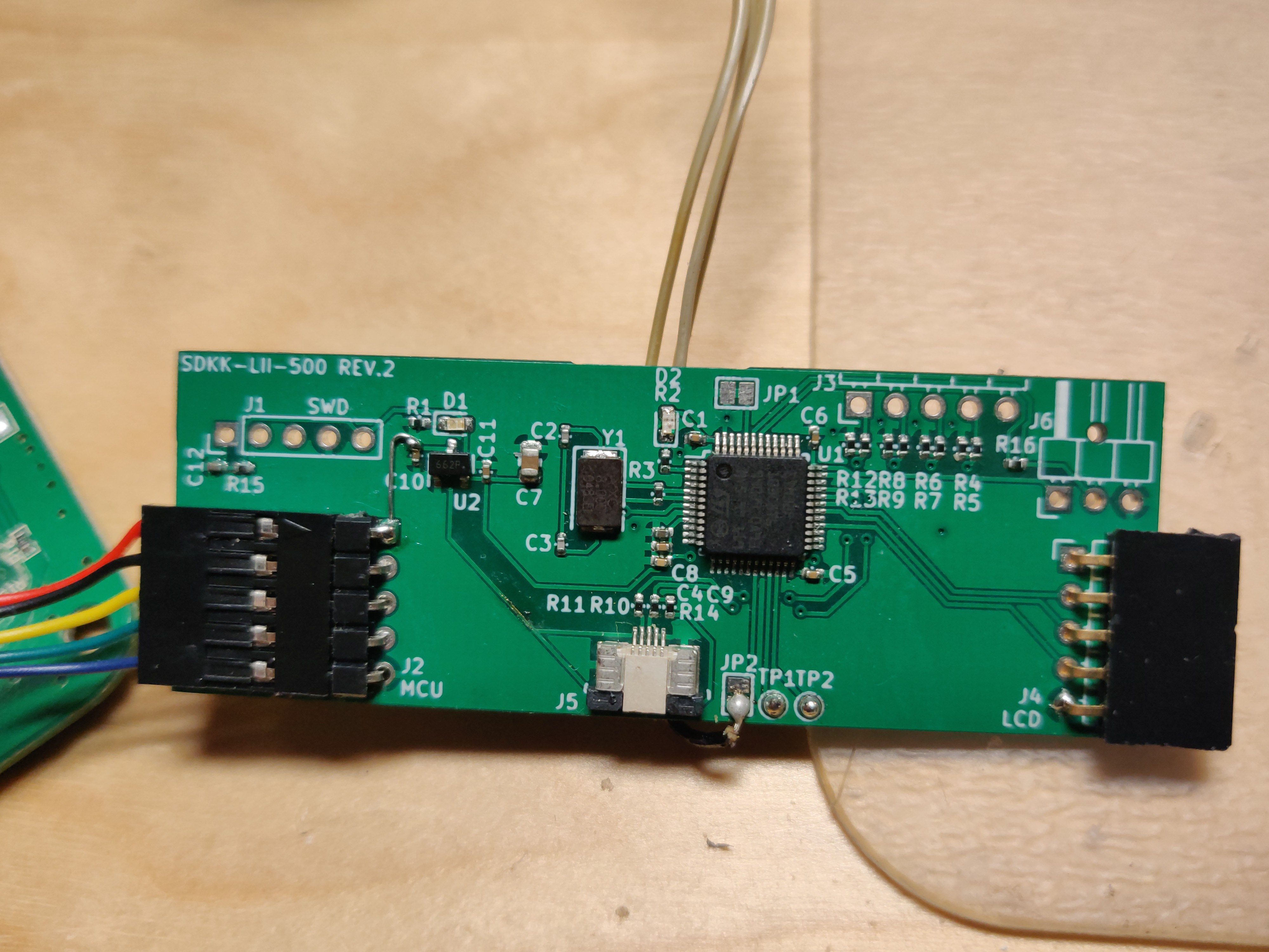
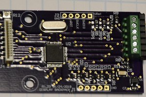
I first thought to investigate the MCU that was inside the charger but unfortunately the chip is unmarked. I could just get rid of it and wire in my own MCU but I figured that I don't want to modify the charger this heavily in case I would like to sell it some day. I have however figured out a different idea to get the cell information I wanted - sniffing the communications between the MCU and the LCD screen. Just a small drop-in pass-through board would be required and it would fit nicely in the existing case so this is the route I went on!
3 The LCD and its interface
3.1 Electrical
I have found that some of the LCD modules had unmarked controller chips on the back of the board:
However, by disassembling the next charger I discovered that it's LCD module contained a marked chip as the LCD controller:
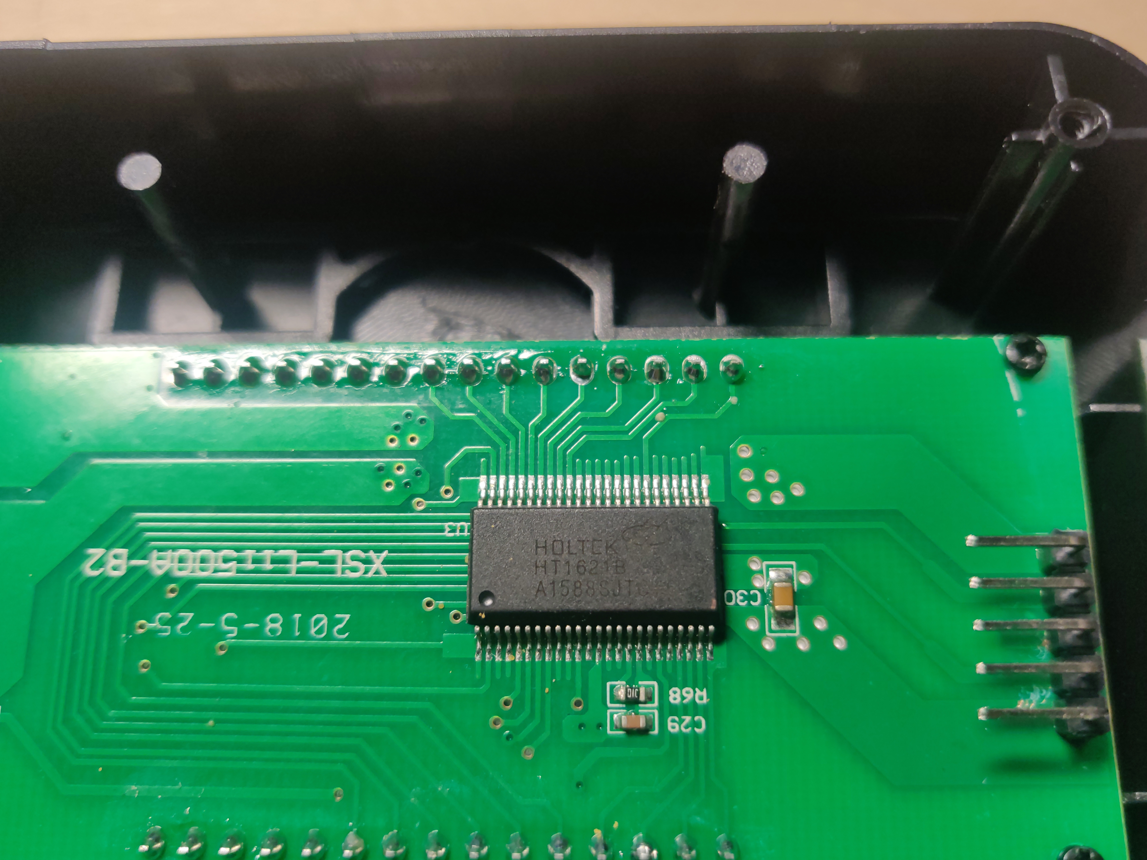
The chip is Holtek 1621B the datasheet is easily found. As I have previously reverse engineered the protocol from scratch I was happy to find that everything matches with what the datasheet describes. The LCD driver chip has much more features than are used by the MCU (for example a watchdog timer). The one interesting tidbit is that the LCD driver chip contains no GPIO pins to drive a transistor controlling the backlight. What the designers choose instead is to reuse the buzzer outputs for the backlight driver. When the LCD backlight enable command is sent the buzzer output is configured to output a 4 kHz tone for the buzzer which I assume drives the backlight transistor.
For posterity I have left all of the reverse-engineering process description below.
By virtue of educated guessing (wide traces -> power ;) and connecting a logic analyzer I have figured out that the interface here is a rather slow one-directional SPI data flow, the pinout of the LCD module is the following:
| Pin number | Color | Signal | Notes |
|---|---|---|---|
| 1 | Red | +5V power | |
| 2 | Black | MOSI | |
| 3 | Yellow | SCK | Frequency is 62.5 kHz |
| 4 | Green | /CS | |
| 5 | Blue | GND | |
| 6 | Not present but marked on... |


 Bharbour
 Guillermo Perez Guillen
 Yann Guidon / YGDES
Is this correct when you wrote:
"as it can reliably handle"?
Maybe you actually meant:
"as it can NOT reliably handle"?