My father likes to create models of all his past vehicles (mostly boats), then he asks me to turn them into running remote control models.
He now has a sail boat, 2 speed boats and recently presented me with a canal boat to electrify.
I did create models of a beach buggy that he created in the 70s, I tried putting an ESP8266-12 based controller in 1 of them, controlled by phone, but it didn't really work as well as I would like.
So, I'm trying again, this time ESP8266 based joystick controller and ESP8266 based device. I actually have ESP-M2 modules as basis for both ends.
The project has been on-going for a few weeks.
I have the controller hardware fully working. It has a small 800mA Lithium ION (LIPO) battery, with a USB mini connector that allows charging using TP4056 charging chip and RGB LED which shows red whilst charging, green when charged. It has a power on switch. It has a 0.96 inch 80 x 160 LCD and an ADS1015 to read the position of the analogue joystick.
The PCB is 48 x 23 mm.
I have a 3D printed case that works well.
I have the device hardware fully working. It has 2 off 1200mA Lithium ION (LIPO) batteries.
There is a small charging PCB 29 x 21 mm. It connects to both 3.7V batteries and has 7.4V output. It contains relays and 2 off TP4056 charging chips, both with RGB LED status and 1 off USB mini connector. It also contains a switch to turn the 7.4V output on/off.
Plug in the USB and the relays connect the batteries to the chargers and the system charges. With USB unplugged the switch gives 7.4V output to model.
The charging PCB is meant to go on top as UI for the model.
I am currently using a standard RC ESC at £1.54 each from Aliexpress, it is 24 x 24 mm and should go under charging board.
There is a main device PCB 30 x 23 mm. It has 4 standard RC connectors (4 Channel), but I am only using 2 of them. Ch1 (up/down) is connected to ESC to control motor. Ch2 (left right) is connected to a standard servo. It contains the ESP-M2 controlling 4 channels via a CD40109 level shifter (channels at voltage supplied by ESC, ESP-M2 at 3V3). 3V3 is supplied by BA033 regulator. The ADC of the ESP-M2 is setup so it can read the 7.4V level.
Both ESP-M2 based PCBs have 7 pin 0.1" pitch programming headers.
I have created a simple programming board containing a slide switch and push button to connect the ESP-M2 to standard FT232 boards, I created 2 of these.
I had some problems with glitches, so I recently added 100nF capacitors to all ADCs.
The PCBs are all designed in KiCAD, I have been etching the PCBs at home for all prototypes so far. But I am now confident and have ordered 5 off of all PCBs to be made by Elecrow, this is the 1st time that I have ever had PCBs professionally made.
The cases are designed in OpenSCAD and 3D printed on a Geetech i3 printer in PLA.
The software is all in Arduino. It is all working. The device is a WiFi server / Hot Spot. The Controller is a WiFi clinent. I have UDP from client from server. The joystick Horizontal and Vertical position is turned into percentage (-100% to 0 to +100%) and sent to server over UDP when they change. The server accepts the horizontal and vertical values and drives the channels. Left/Right moves the servo through full range, Up/Down drives the motor via the ESC.
Currently the LCD is showing the controller battery voltage and joystick ADC and percentages. I need the device to read it's 7.4V battery and send to controller (thinking another UDP going other way). I need the controller to alter LCD, I want battery symbols for both controller and device with level, green level, amber level for storage voltage range, red for near flat, get to safety. I want signal strength symbol.
I need a case to hold 2 LIPO batteries in model.
I need a case to hold stack of 3 PCB in model.
Once I have the Canal Boat model fully working and back with my Father then I have a fully 3D printed monster truck style car that I would like to resurrect, use this...
Read more »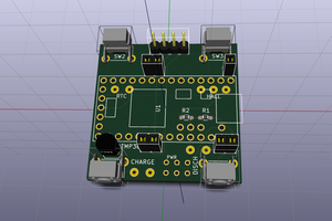
 Matias N.
 Jeroen
 Xasin
Xasin
wot, no comments?