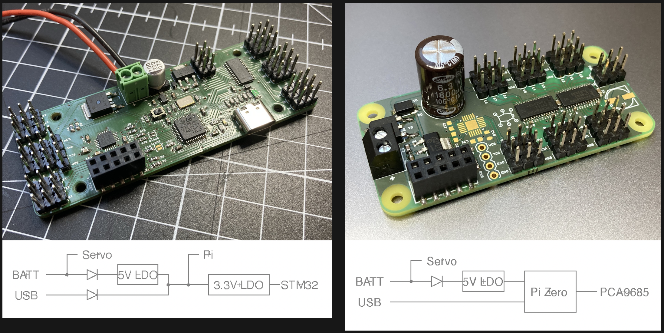
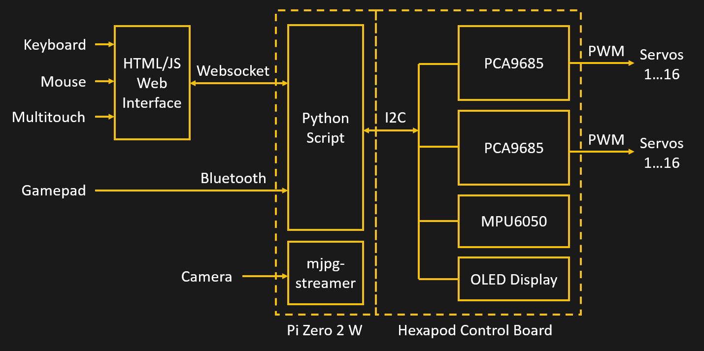
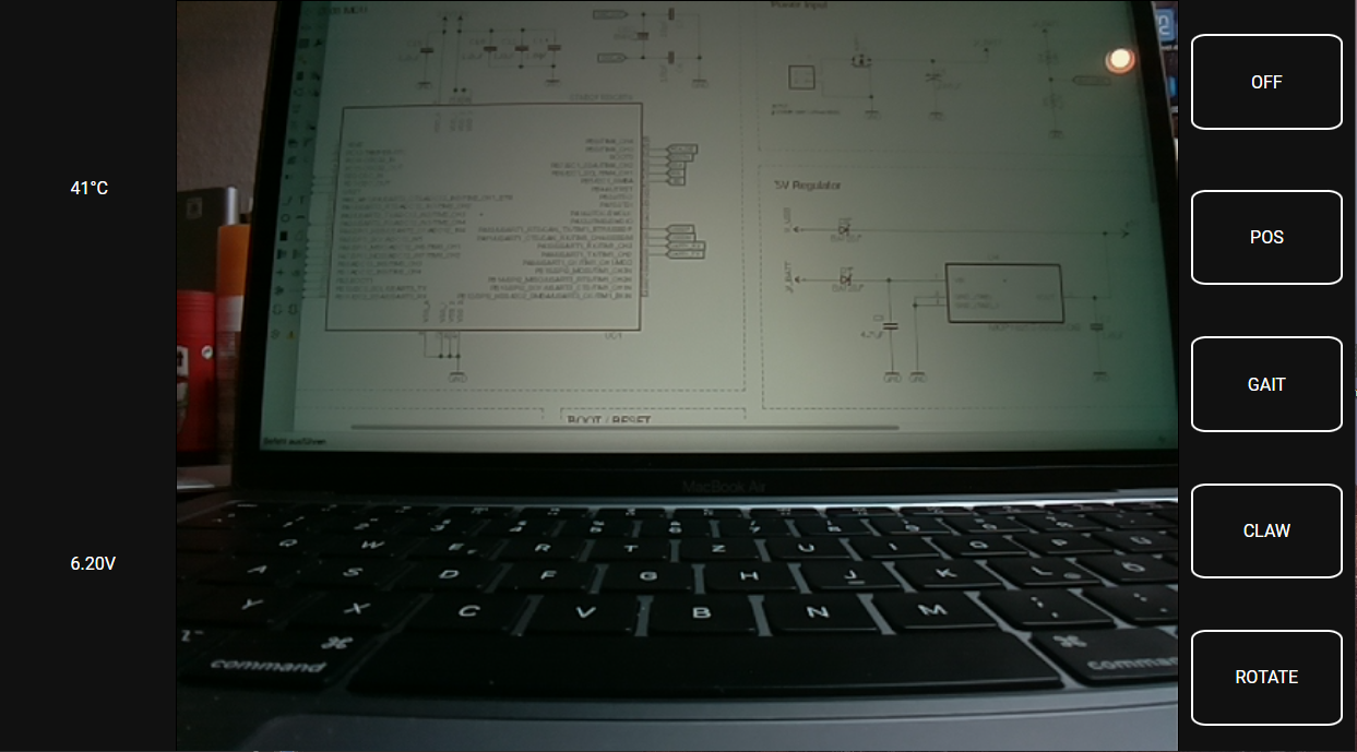
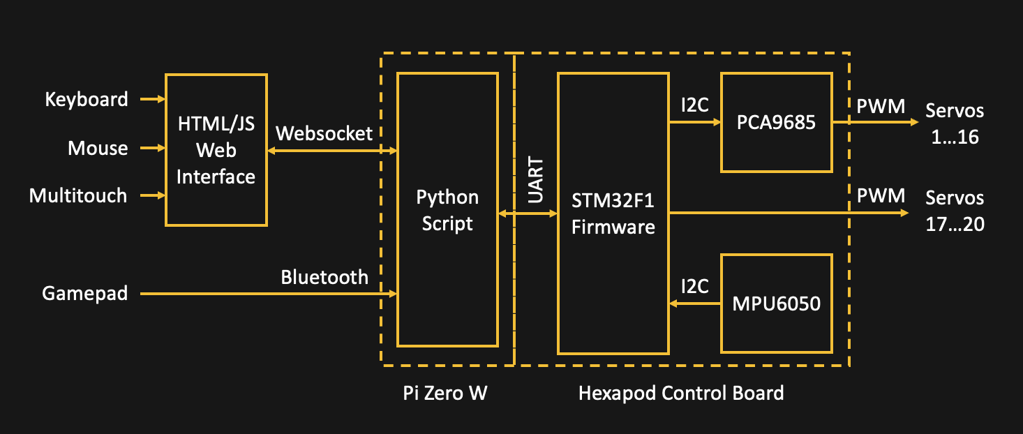
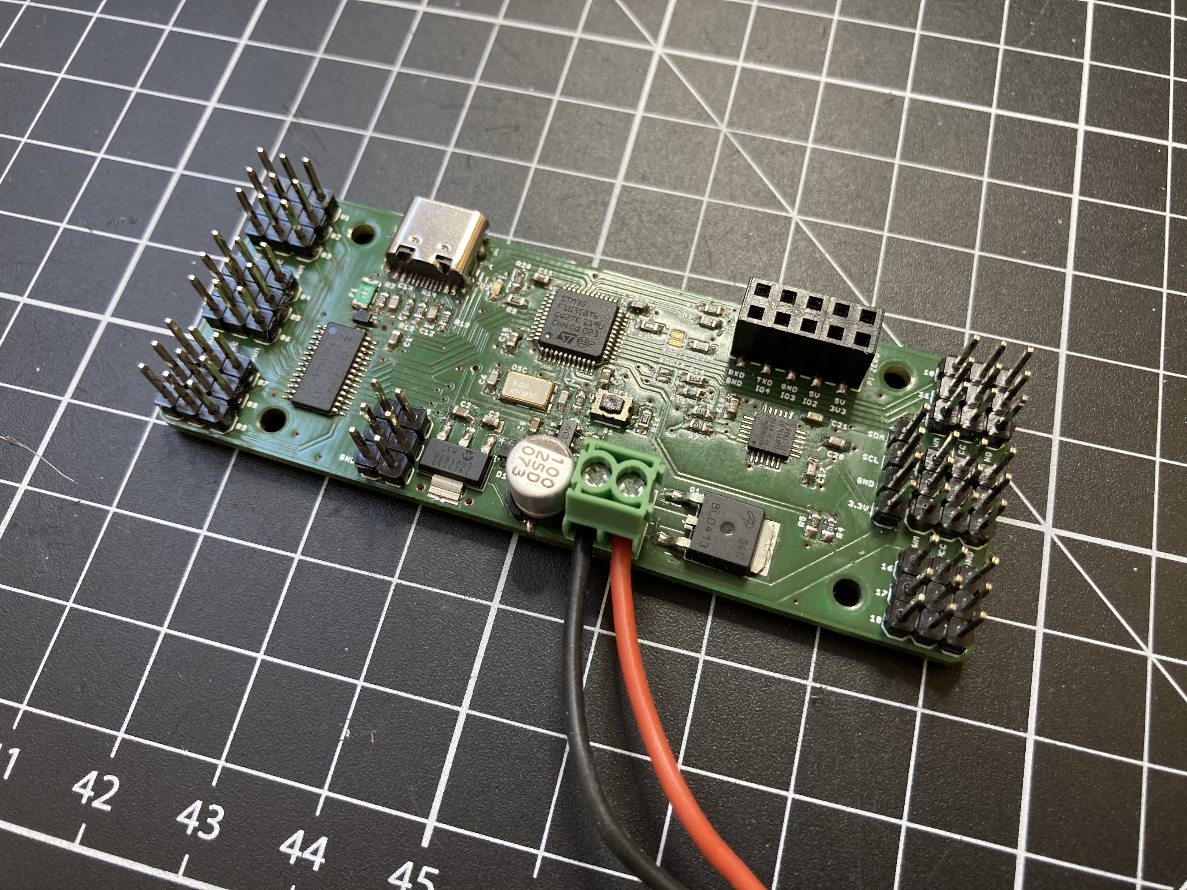
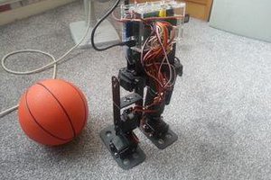
Close
0%
0%

ZeroBug - DIY Hexapod Robot

3D Printed Micro-Servo Hexapod

Similar projects worth following
ZeroBug is a 3D-printed micro-servo hexapod robot powered by a Raspberry Pi Zero and a STM32F103. The Pi Zero is in charge of the input methods and front end, making the robot controllable via mouse, keyboard, multitouch or simply a Bluetooth Gamepad. To get the robot walking, the STM32 handles leg locomotion, inverse kinematics and controls its 18 servos. All of these calculations run at 50Hz, enabling the Hexapod to move smoothly and with high precision. Its compact frame is fully 3D printed.

Some of the key features:
• Custom locomotion engine
• Compact CAD design and 3D printed components
• Web interface with keyboard, mouse and multitouch input via websocket
• Bluetooth game controller support
• Claw for object manipulation
• Cheap to build with standard hobby servos (outside the global chip shortage at least)

PCB layout, source code and STLs on Github: https://github.com/CoretechR/Zerobug

  • An STM32F103 does the heavy lifting when it comes to making the robot walk. It calculates locomotion, inverse kinematics, body rotation/translation and finally drives the servos. With a simple serial protocol, commands can be sent to control the robot directly. The serial interface is also what the Raspberry Pi Zero W is connected to. It is running an improved version of the software created for the wheeled Zerobot, which hosts a web interface for mouse and touch controls. On top of that, wireless gamepads are supported via pygame. 
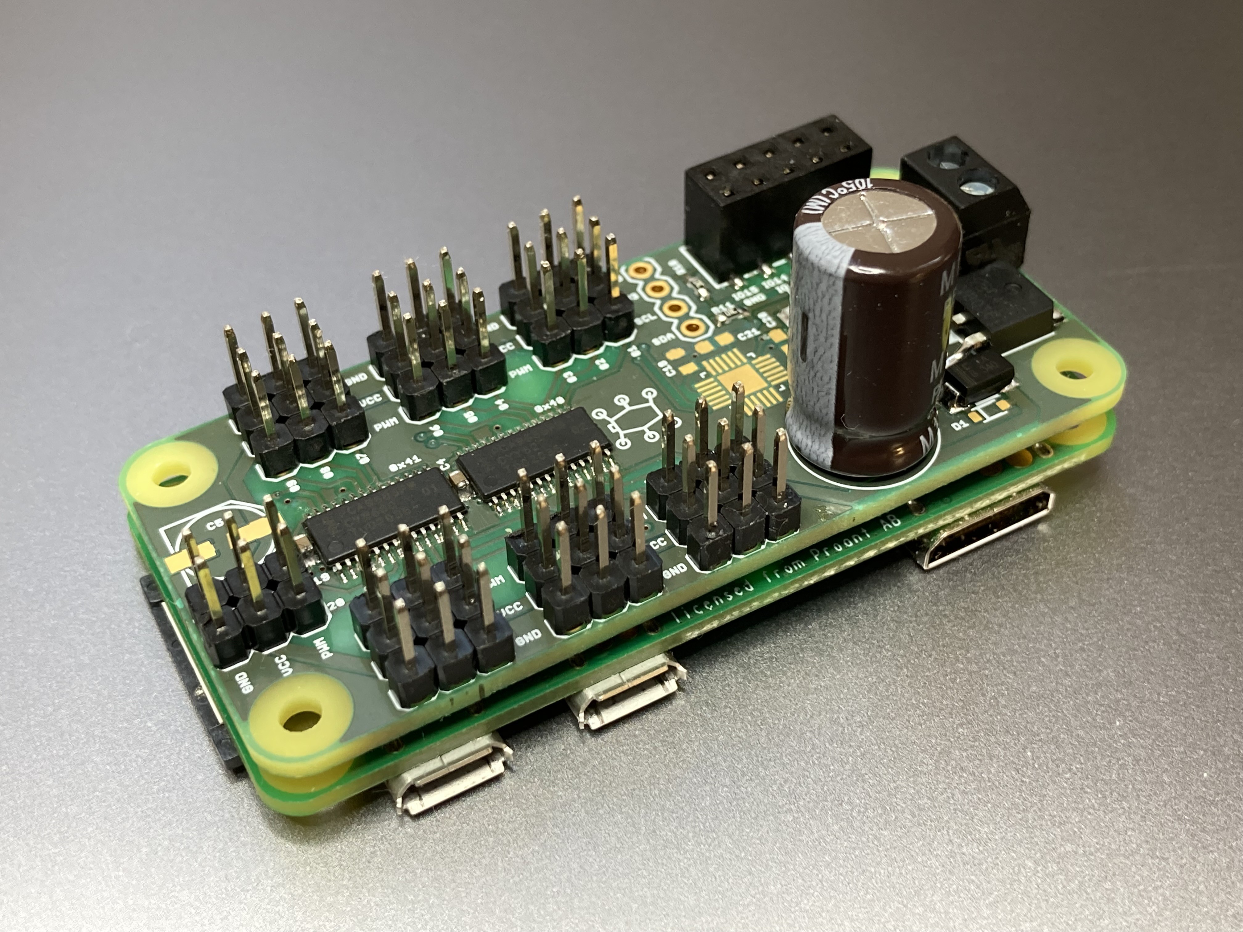
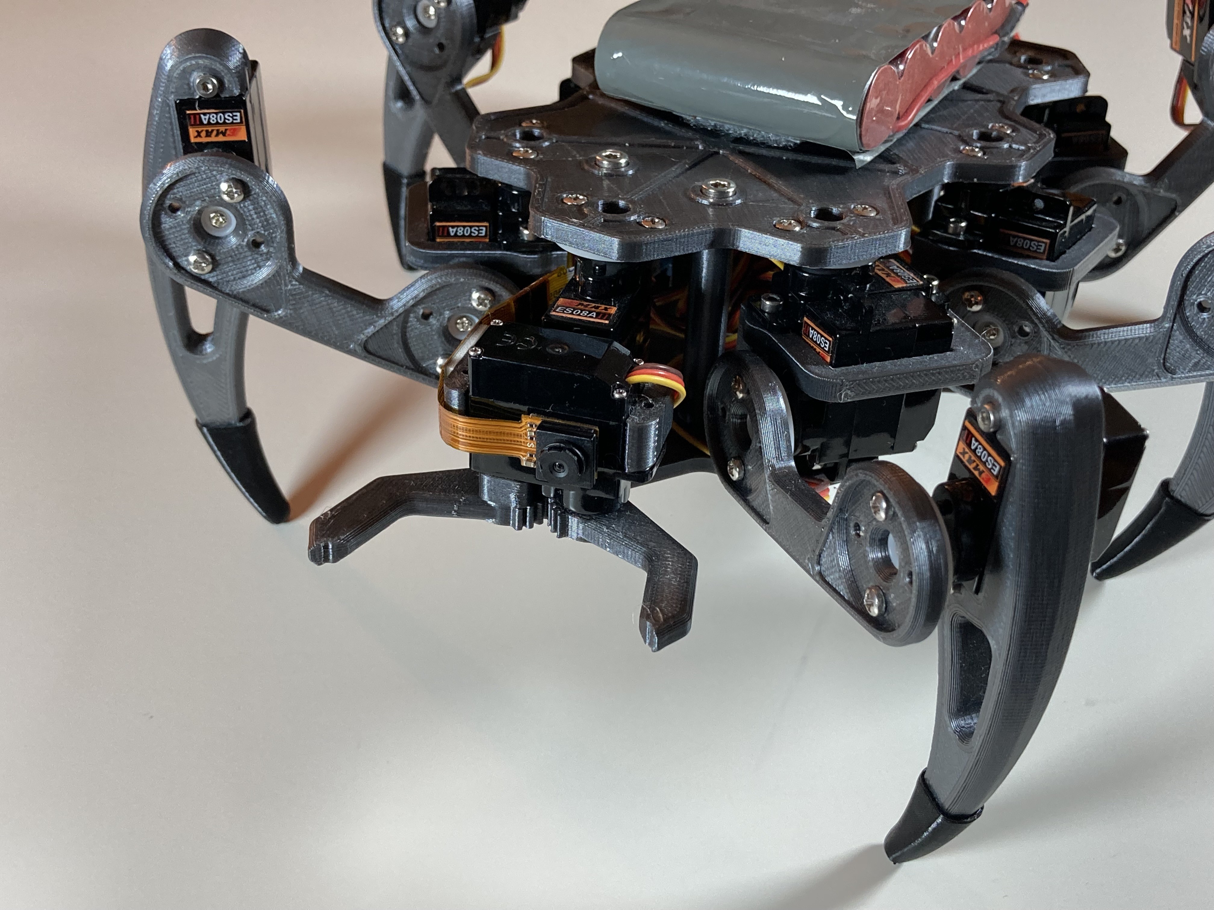
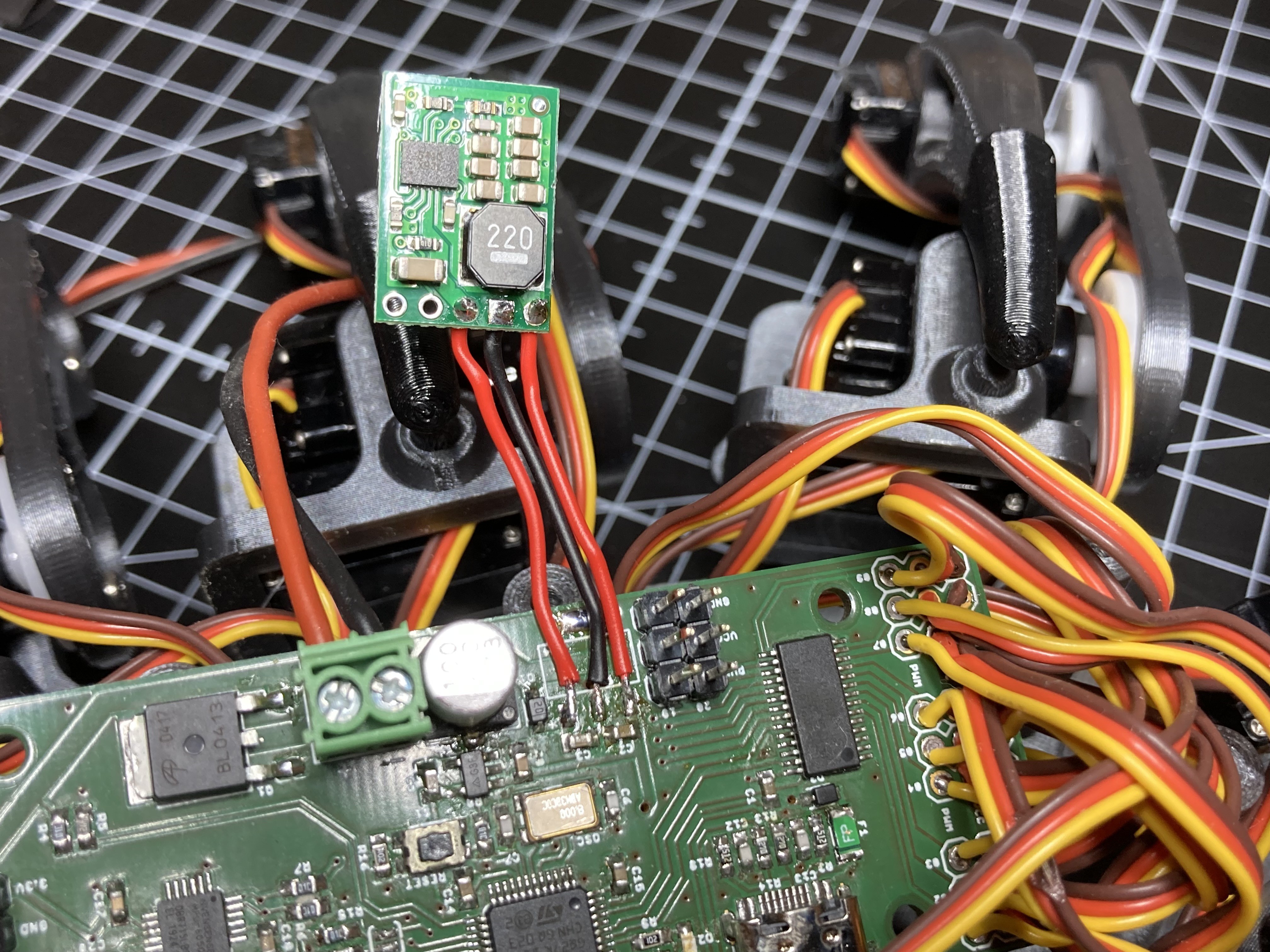
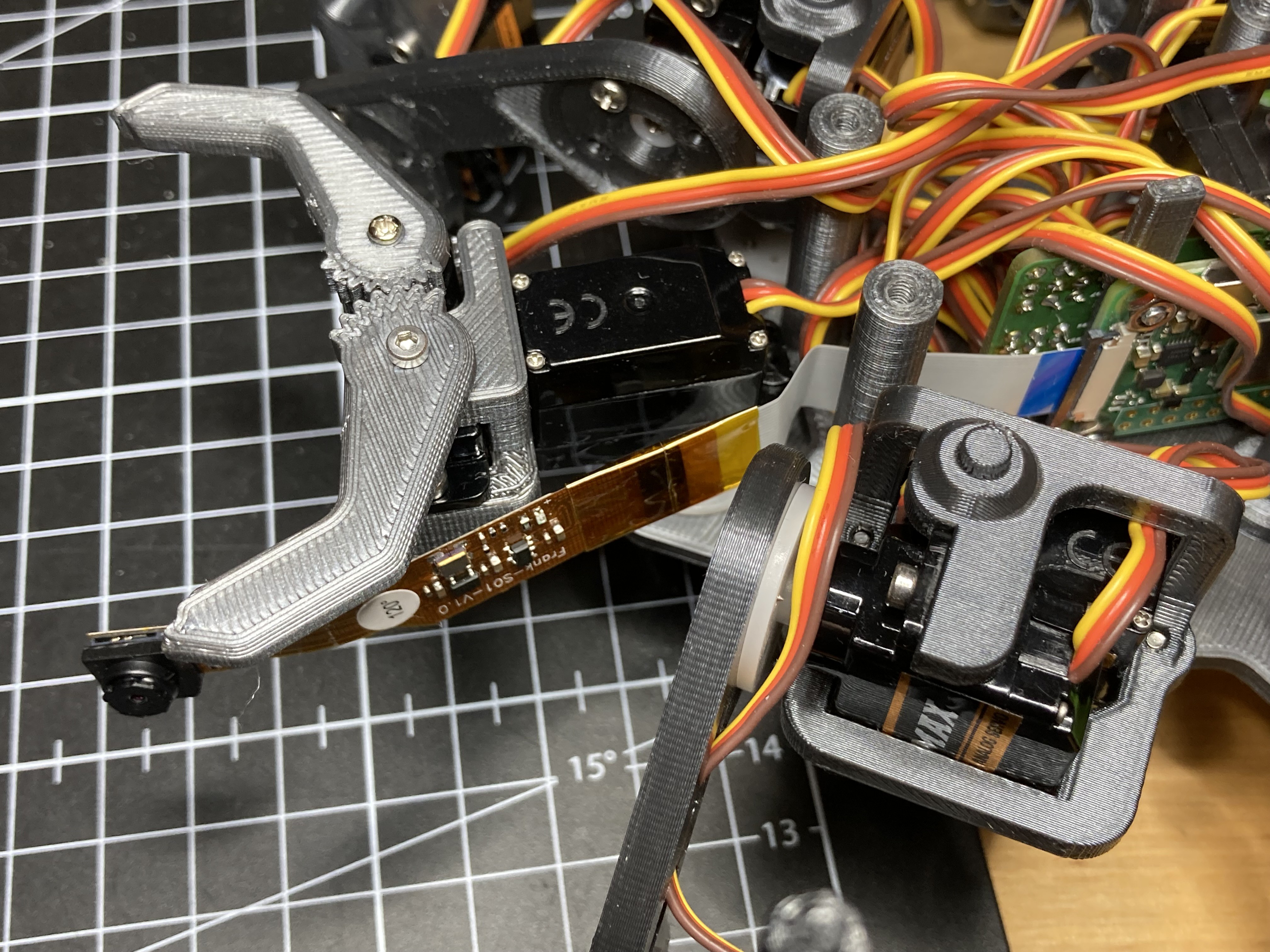
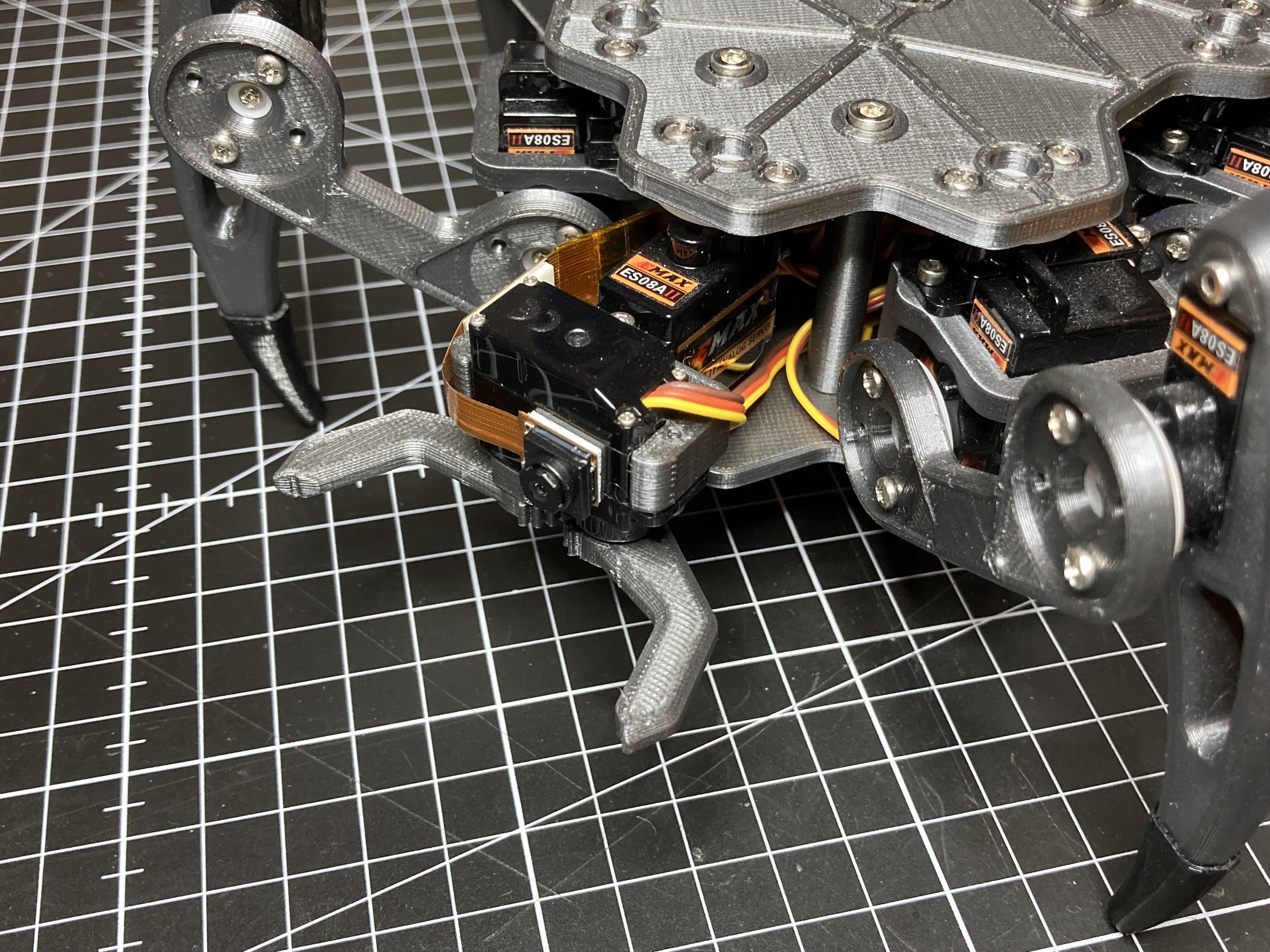
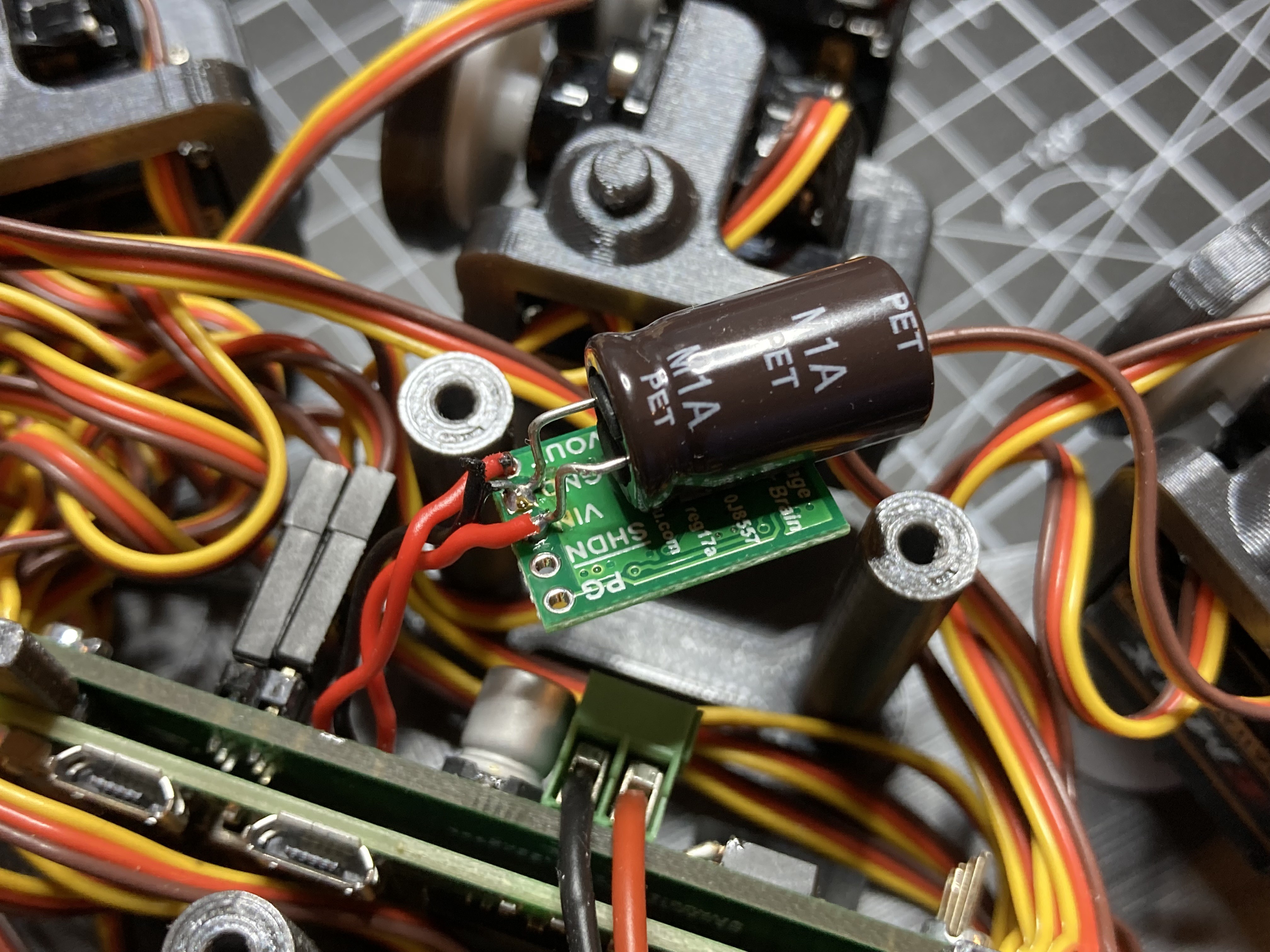
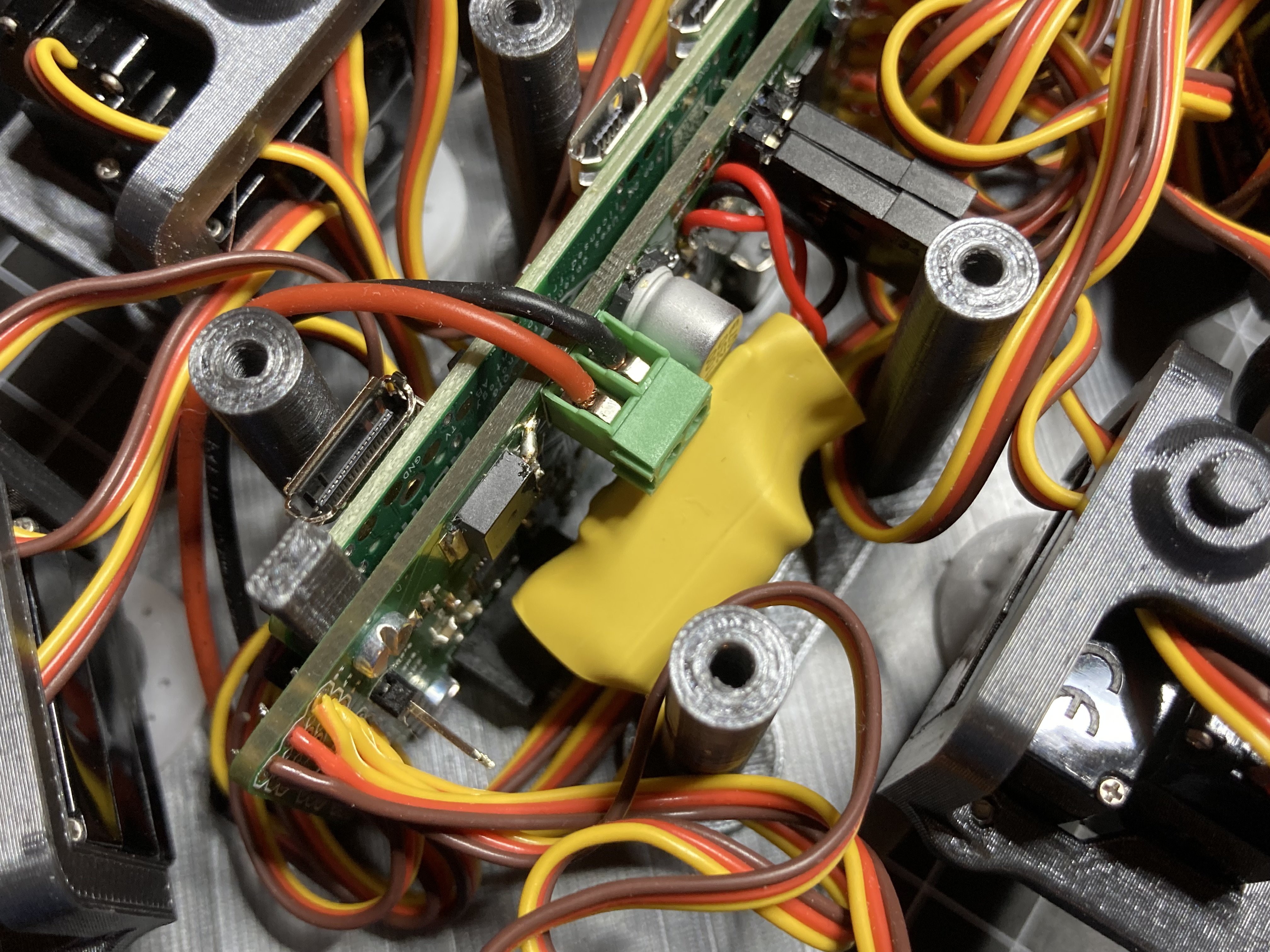
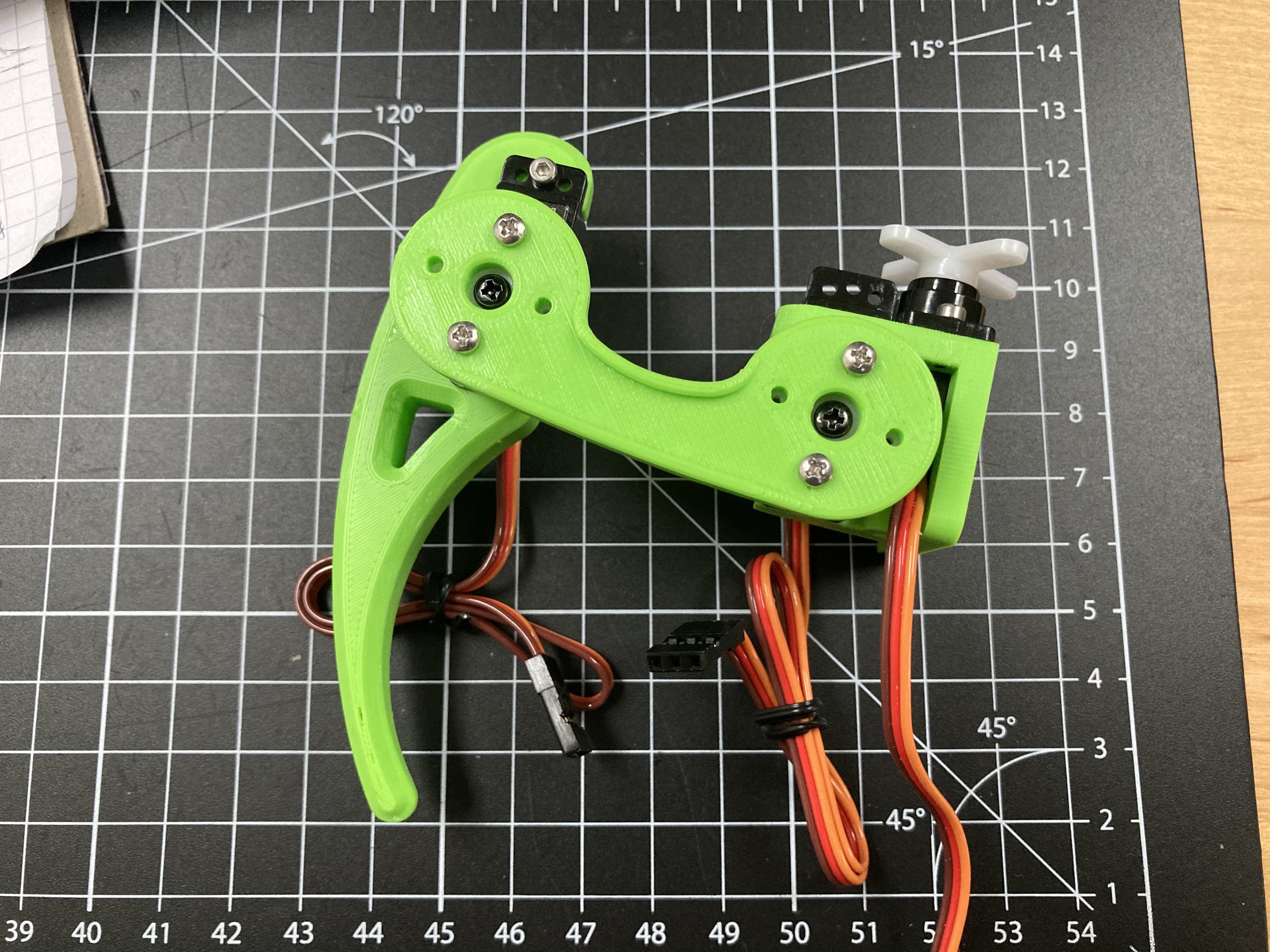
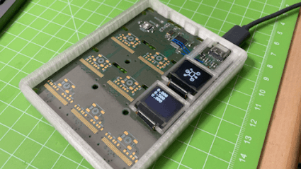
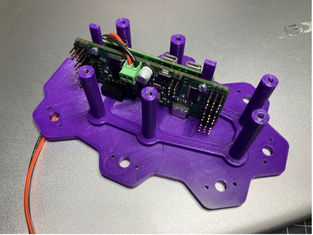
  • Hardware-wise a custom circuit board holds the STM32, the PWM controller and a few other components while the Raspberry Pi Zero is plugged into the back of the PCB. The servos used are inexpensive EMAX ES08A II. Anything apart from the electronics and servos is 3D printed.

The whole project is heavily inspired by Matt Dentons incredible µBug, adopting its dimensions and proportions.

  • 1 × • STM32F103C8T6
  • 1 × • Raspberry Pi Zero W
  • 20 × • EMAX ES08A II Micro Servos
  • 1 × • Custom Circuit board
  • 1 × • NXP PCA9685 PWM Driver

View all 7 components

  • ZeroBug Lite

    Max.K01/29/2022 at 15:59 0 comments

    With the chip shortage still raging on, building a ZeroBug with the rare STM32F103 is becoming increasingly difficult. I was looking for a replacement for a while, even considering an ESP32. But now that the powerful Raspberry Pi Zero 2 is here, an additional microcontroller might not be necessary at all to control the servos. To experiment with a Raspberry-only approach I created a new PCB.

    Removing the microcontroller means that the Raspberry Pi has to control the servo driver by itself.  That’s why a second PCA9684 PWM-driver is needed. The i2c pins are conveniently positioned on the existing connector so no change is needed there. The microcontroller and its USB port together with lots of smaller components are no longer needed. With much fewer parts, the PCB can be shrunken down the the Pi-Zero size. By using the Pi’s internal 3.3 voltage, even the 3.3V regulator can be taken out (the board still needs a 5V LDO to power the Pi). I also put in a chunky 1.6 mF capacitor to make sure the Raspberry Pi doesn’t reset while the servos move.    

    The new, smaller PCB and the Raspberry Pi can be mounted horizontally in the Hexapod while still leaving room for servo wires.  

    Software-wise a few  changes had to be made. The Raspberry Pi now has to take over all the tasks of the microcontroller that was running the gait engine. To make everything run in a Python environment, I had to port the entire gait engine to the new language. As Processing(.org) features a Python-mode I used this for testing the code (the Python-based simulator is also available GitHub: https://github.com/CoretechR/ZeroBug-Lite). Adafruit has a nice CircuitPython library that makes it easy to control the PCA9685.  

    With everything assembled and programmed, the ZeroBug can walk with only a Raspberry Pi Zero as its brains. How well does it work? I did some testing but cannot say that the „ZeroBug Lite“ version is as reliable as the microcontroller-based one. For one, the output enable signal that tells the servo drivers to stop is only controlled by the python script. When the software is abruptly stopped, the servos can’t be disabled. And as the Pi can’t measure analog signals, there is no way to monitor the battery voltage without additional hardware. The software at least needs more work to build in the same kind of safety checks that were implemented in the original robot.

    If you are interested you can check out the new GitHub Repository: https://github.com/CoretechR/ZeroBug-Lite

  • Upgrading to the Raspberry Pi Zero 2

    Max.K11/20/2021 at 22:15 0 comments

    While I appreciated the small form factor, the performance and boot times of the Raspberry Pi Zero had always been bothering me. When the upgraded Raspberry Pi Zero 2 was announced a few weeks ago I immediately knew this would be perfect for my hexapod. Not only would this speed up the boot time but also enable some new features that were not possible before. 

    The Raspi Zero 2 now features the same quad-core CPU as the Raspberry Pi 3, just under-clocked to 1GHz. Even with the cores slowed down, the new board draws a quit lot more power. Tom’s Hardware tested the power consumption in their early review: https://www.tomshardware.com/reviews/raspberry-pi-zero-2-w-review. Under stress, the current draw rises from 260mA to 370mA. This meant that although the dimensions and ports stayed the same I still had to make some changes to accommodate for the new single board computer. 

    When the hexapod is powered by a 6V-battery, a voltage regulator supplies 5V to the Pi Zero and to the 3.3V-components. I chose a Microchip MCP1825 with 500mA output current which was more than enough at the time. To be on the safe side, I now decided to replace the LDO with a 1A DC/DC converter by Pololu. I still have to test wether this was really necessary. 

    Originally I planned to fit a camera into ZeroBug for streaming video. But as the Raspberry Pi Zero was already struggling with the controller inputs I decided against that. Now with the more powerful Pi Zero 2 the camera would not be a problem anymore. 

    I settled for a camera module by Pimoroni that integrates the 22-pin camera connector. After soldering an extension to the cable I stuck the camera directly to the gripper servo of the robot.

    The new Raspberry Pi Zero 2 worked right away with the same SD card image. But then I noticed a problem: After moving the servos for more than a few seconds the Raspberry Pi reboots itself. The reason for this was quickly determined: When some of the 20 servos are moving, the battery voltage drops below 3V. The old Raspberry Pi Zero was more forgiving in that regard. I solved the issue by including a 1.8mF electrolytic capacitor on the input of the 5V DC/DC converter. The existing diode ensures that the capacitor only buffers the logic components and not the servos.

    With the capacitor in place ZeroBug ZeroBug now only needs a few changes to its software to enable the camera stream. For this I installed mjpeg-streamer and created a batch script that starts the stream. By adding a line to the etc/rc.local file the script is executed during boot up. The web-UI was already prepared for embedding a stream element, so there is nothing more to do than uncommenting one line in the html. You can have a look at the updated code on Github: https://github.com/CoretechR/ZeroBug

    The video streams is a fun addition to the hexapod and together with the processing power of the Raspberry Pi Zero 2 there are many possible applications. Amongst others this includes face tracking and autonomous navigation. Maybe the servos can even be controlled by the Raspberry Pi directly which would render the STM32 unnecessary.

  • Combining Hardware and Software

    Max.K06/27/2021 at 09:30 0 comments

    Porting the locomotion code from the Processing simulation to the STM32 was relatively simple. Some safety checks had to be added to prevent the robot from accidentally crashing its legs into each other. The microcontroller manages the calculation for the locomotion, rotation, IK and everything else in just under 20ms. Surely some optimization is possible to make it run even smoother. 

    I wrote a simple protocol for controlling the STM32 over UART. This protocol can be used to receive commands either from USB or from the Raspberry Pi Zero. The Raspberry Pi runs a python script that handles the Websocket communication, UART and pygame. As soon as a client connects to the Pi, a website is loaded that can be used to control the hexapod with keyboard, mouse or touch inputs. Pygame allows for a Bluetooth connection with a game controller. The Raspberry Pi translates the commands and sends them via serial to the STM32. The Pi also sends a periodic heartbeat signal, so the STM32 can stop the servos in case the Raspberry Pi freezes up.

    This combination of Raspberry Pi and microcontroller works really well. Controlling the hexapod is a lot of fun, especially with an Xbox controller. You can see a video below of how the controller is mapped to the hexapod axes:

    Overall, I am happy with how this project turned out. The hexapod walks like I wanted to and can be controlled with surprising precision. The development didn’t always go as smoothy as it might appear from reading these project logs. I actually started working on a simulator in 2014 and shelved the whole project out of frustration, only to dig it up a few years later. Just at the start of this year it really clicked and I got the motivation to go through with the project. In retrospect the ESP32 might have been a possible replacement for both the Raspberry Pi and the STM32. Performance and compatibility with game controller might be an issue though. 

  • Moving on to Hardware

    Max.K06/27/2021 at 09:30 0 comments

    With the simulation done it was time to move on to the physical hexapod robot. I started designing parts for a single leg and searched for fitting servo motors. Since there are 18 servos needed for this hexapod, they define the total cost of the robot. I settled for some cheap Emax ES08A II micro servos. They are quite powerful for their size and their plastic gears seem to be holding up well so far. I paid around 80€ for the entire set of servos. When using proper smart servos for robotics, a single unit can cost this much. 

    Although they are “micro”, these servos can draw a lot of current. I was planning to use a lithium battery first but later switched to NIMH. The huge advantage is that six 1.2V NIMH cells add up nicely to 6V which the servos need. A lithium battery requires a voltage regulator, and with the high current demand that just complicates the project unnecessarily. 

    To drive the servos 18 PWM outputs are needed. At first, I tried to find a microcontroller with enough IO to connect the servos directly. The Teensy 4.0 might have been a good candidate for this. However, the robot has very limited space for electronics and the Teensy board just didn’t seem to fit right. The STM32F103 was the next best choice as it is Arduino-compatible and I had already gathered some experience with my macro keyboard. Because of the limited IO and timers, a PCA9685 PWM driver is used to control 16 servos while the remaining four can be handled by the STM32 itself. You can view the hexapod software running on a macro keyboard prototype below:

    With the microcontroller selected, the robot still has no way to be controlled from the outside. To add wireless connectivity, I decided to include a Raspberry Pi Zero W. For my Pi Zero-based Zerobot robot I had already created software for a web interface, and I figured that adding a Bluetooth game controller should not be a problem. With the most important parts selected, I went on to create the PCB.

    On the ZeroBug board, the microcontroller and Raspberry Pi are connected via UART. I am using a bottom-entry pin header. This allows for a very compact assembly without having to solder the Raspberry Pi. The STM32 can be programmed using its USB interface, while the Raspberry Pi is using its WIFI connection for access via SSH or VNC Viewer. 

    Supplying the components with power was tricky, as I wanted to be able to supply the board with either a USB connection or the battery. This is done by creating a diode-OR circuit (see picture below): With only USB attached, the Pi supplied with (almost) 5V, which it internally drops to 3.3V anyway. Additionally, the STM32 gets its own 3.3V regulator. When the battery is connected, it powers the servos directly through a simple reverse polarity protection. An additional 5V LDO supplies the Raspberry Pi and microcontroller. In reality this worked out great. Only with a very low battery, the Raspberry Pi might reset during quick movements. For this reason I am measuring the battery voltage with the STM32. 

    When orienting the parts some aspects had to be considered: The USB socket must be easily accessible. The servo connectors had to be positioned to minimize wire lengths. To get the Raspberry Pi’s antenna out of the way of motors and the battery, I had to point it towards the ground. Finally, the camera connector is oriented to the front of the robot so a camera can be attached later. I overlooked how long the pin headers for the servos are and together with the servo plugs they are too big to fit into the robot. Because of that the servo cables had to be soldered on later.

    I managed to fit all the components on two-layer board. There was even space left for a MPU6050 motion sensor and a connector for I2C OLED displays. The connector came in handy for testing as an OLED screen can show the state of the legs without having to power the servos.

    While I was waiting for the PCBs to arrive, I continued...

    Read more »

  • A Walking Simulator

    Max.K06/27/2021 at 09:29 0 comments

    One mistake I had made with my earlier quadruped robot was to build the hardware without knowing how the software could be done. For this project, I wanted to be absolutely sure that I could get the robot to walk before investing time and money into a physical prototype. And the best way to do this is using a simulation. Instead of a specialized robotics simulator I decided to go with Processing again, which I had already used to create a simulator for my quadruped robot. Processing is a programming language and IDE very similar to Arduino, only that it is based on Java instead of C++. To me one of the biggest benefits is that the languages are so similar that code developed for a Processing desktop application can be easily ported to Arduino with only minor modifications. 

    I started with a very simple animation of a robot’s leg moving, then added more and more complexity until the hexapod was moving properly. You can see a little supercut of the development process below:

    The most difficult part was figuring out the locomotion. As the speed, direction and rotation of the movement are variables, the hexapod has to determine what legs to move to what position at a given time. Now my implementation of a locomotion engine works like this:

    Each leg has tree coordinates: A default position, a starting position and its current position. The default is the coordinate that the leg will try to resume. With every leg at this default position the robot’s is in a neutral pose. When the hexapod starts to walk, its legs first move opposite to the body. This means shifting the starting and current position while the legs are on the ground. Obviously without the legs making a step they will exceed their range of motion very quickly. To determine which legs to lift a gait sequence is used. This is nothing more than a lookup table that says which leg can take a step at what time in the sequence. If it is a leg’s turn to step, the starting coordinate is frozen. The leg now follows a path between the start coordinate towards the default position until it has reached its target. The step height is determined by the progression along that path, making the leg move in the shape of an inverted parabola. As the code loops through the gait sequence, each leg tries to catch up with the body’s movement, trying to reach their default positions.

    This is the simplest approach I could come up and it’s enough to make the robot move quite smoothly. After developing this locomotion function, the rest is fairly easy to implement. To make the hexapod move and rotate statically, the leg coordinates get translated/rotated around the body’s center point. To determine the angles for the leg joints, inverse kinematics are calculated. While this might sound complex, it’s just basic mathematical equations that have to be performed for each leg.

    For the simulator, Processing’s 3D rendering is used to display the hexapod either as a wire mesh or with its later CAD files. Controlling the robot is done via mouse and keyboard. This was more than enough to get a sense of what the walking would look like without the need for any hardware.

  • Introduction

    Max.K06/27/2021 at 09:29 0 comments

    Ever since the first videos of Boston Dynamics’ creations started showing up on the internet, I have been fascinated with legged robots. Back in 2013 I created a quadruped robot. The project progressed until the robot could stand and do some very basic walking. But it turned out to be really difficult to develop proper walking gaits and the servos seemed to struggle with the weight of the robot. The decision to go with four legs instead of six was mainly due to the cost of servo motors. However, six legged robots have a big advantage: Unlike quadrupeds they can lift three of their legs while the remaining legs form a stable tripod. This eliminates the need for constant weight shifting and balancing.

    There are lots of Hexapods out there, ranging from small research projects to commercially available kits. One of them that stood out to me from the beginning is Matt Dentons µBug. Denton has been making hexapod robots since the early 2000s and has since perfected them to the point where they were even used in movie productions. Their organic, insect-like movements are something very few robots get right. And since I saw the videos of these robots, I wanted to build one myself. While the uBug was once sold as a kit, the shop and forums have long gone offline. So I tried to find what was left of the documentation and decided to build my own hexapod from scratch.

View all 6 project logs

Enjoy this project?

Share

Discussions

littleboy2333 wrote 04/04/2024 at 10:10 point

hello,I use the relaese version of software.but i don't know the vnc ursename and password,can you tell me.thank you.

  Are you sure? yes | no

natedogg182 wrote 08/06/2023 at 04:29 point

I’m very new and green but is there a specific board for the stm32 and the NXP PCA9685 PWM Driver I should buy because I find multiple boards for both when I search and an not sure which to get.  Please excuse my ignorance. I’m using the original raspberry pi zero w not the zero 2 for this build. Thank you

  Are you sure? yes | no

Kent wrote 07/22/2023 at 12:42 point

Are you willing to share the original design files for the printable parts? I'm looking to make this using MG92B servos and need to adjust some of the part dimensions.

  Are you sure? yes | no

Kaitanako wrote 05/10/2023 at 19:49 point

Thanks for sharing the great project. I made the Zerobug lite model and it worked flawlessly. I tried to convert zerbug lite to zerobug project working with stm32 but I could not establish serial connection between stm32 and raspberry pi. Raspberry pi and stm32 seem to work fine, but there is no movement in the motors. I'm new at this so I need some help. Have you used any ttl adapter for serial connection and which pins on stm32 should contact which pins on raspberry pi? I would be grateful if you could share a detailed Serial wiring diagram about it.

  Are you sure? yes | no

Max.K wrote 05/17/2023 at 16:23 point

Hi, it awesome to hear that you built the robot! I'd love to see pictures of it!
On the PCB, UART1 of the ESP32 is connected to the UART TX and RX of the Raspberry Pi Zero (PA10 -> GPIO14 and PA9 -> GPIO15). The UART is running at 115200 baud.

You should be able to see the commands being sent by the raspberry using a TTL usb adapter.

  Are you sure? yes | no

Kaitanako wrote 05/20/2023 at 20:40 point

It's not quite ready but if you give me a communication tool I can send you photos and videos showing its current status. I think I have a few issues to solve and I might need help with that. I do not think that the feet are fully synchronized, the ds4 commands I use for control do not work properly, I need to make a setting regarding these issues.

  Are you sure? yes | no

Kaitanako wrote 04/18/2023 at 00:48 point

How should I calibrate the servo, is there any tool or will it be manual?

  Are you sure? yes | no

Max.K wrote 05/06/2023 at 08:08 point

There is no special tool for calibration. I just set all the servos to 80° angles and adjusted the offset until they were all in a right angle.

  Are you sure? yes | no

Momie wrote 12/07/2022 at 14:16 point

Hello,

Marvellous project.

I see that it is possible to oder the PCB.

Otherwise, is there a possibility to get a welded one with the components ?

I'm not skill enought to weld such PCBs :-)

  Are you sure? yes | no

jasonsand wrote 06/08/2022 at 15:52 point

If I ran 2 PCA9685 16-Channel 12-Bit PWM Servo Driver boards, soldered all the connections to save space inside, how would the code need to be adjusted? Could I run one side of servos on one and then the other for the other side?

I am looking at these https://www.aliexpress.com/item/32811125110.html?spm=a2g0o.productlist.0.0.2062198cbAgki7&algo_pvid=7c697d51-54b3-4adb-bc02-9a070f00ac49&algo_exp_id=7c697d51-54b3-4adb-bc02-9a070f00ac49-25&pdp_ext_f=%7B%22sku_id%22%3A%2264583513452%22%7D&pdp_npi=2%40dis%21CAD%21%214.59%21%21%213.07%21%21%400b0a555416547028114402190e01ef%2164583513452%21sea

and I will add these capacitors https://www.aliexpress.com/item/1005004224701993.html?spm=a2g0o.productlist.0.0.4b116f33hX2KGo&algo_pvid=d363757a-56fe-4a3f-aed0-78f83a86da54&aem_p4p_detail=2022060808420210535781539639300004788250&algo_exp_id=d363757a-56fe-4a3f-aed0-78f83a86da54-30&pdp_ext_f=%7B%22sku_id%22%3A%2212000028439551966%22%7D&pdp_npi=2%40dis%21CAD%21%2117.94%21%21%21%21%21%400b0a556e16547029227774221e2a23%2112000028439551966%21sea

I also adjusted the stl files to fit this servo. https://www.aliexpress.com/item/1005003788629887.html?spm=a2g0o.productlist.0.0.f8a63242PyxXA1&algo_pvid=c26740ba-9d0d-4a04-8f9f-89da56f2e1e4&aem_p4p_detail=202206080854192194297164582840027421286&algo_exp_id=c26740ba-9d0d-4a04-8f9f-89da56f2e1e4-13&pdp_ext_f=%7B%22sku_id%22%3A%2212000027172151416%22%7D&pdp_npi=2%40dis%21CAD%21%2133.9%21%21%218.16%21%21%40210318cb16547036594631353e4493%2112000027172151416%21sea

I am looking at making this robot in my high school robotics class next year.

  Are you sure? yes | no

Max.K wrote 06/11/2022 at 09:33 point

Using two servo drivers should be easy. You just need to use different i2c addresses and declare another instance of the PCA9685 in the code like this:

Adafruit_PWMServoDriver pwmA = Adafruit_PWMServoDriver(0x40, Wire);

Adafruit_PWMServoDriver pwmB = Adafruit_PWMServoDriver(0x41, Wire);

The chip crisis has become really annoying for hobby projects. The esp08a servo, the stm32f103 and the Raspberry Pi are basically all sold out. I hope you will find all the parts you need!

  Are you sure? yes | no

Scan-87 wrote 02/01/2022 at 06:37 point

Hi there! I'm just curious, have you thouth about using raspberry's GPIO pins to  controll servo drivers directly? As far as I understood, they need only one controlling wire, while the others can be bridged to the power source. And you have about 25 of programmable pins onboard

  Are you sure? yes | no

tony_ccd wrote 09/12/2022 at 11:22 point

You can drive any of the GPIO pins as servos with the PIGPIO library. There's an example on the site: https://abyz.me.uk/rpi/pigpio/examples.html. It has always seemed to me to be a very easy to use library.

  Are you sure? yes | no

josedennis1 wrote 09/30/2021 at 06:02 point

Awesome work bro

  Are you sure? yes | no

Craig Hissett wrote 09/23/2021 at 18:36 point

This is amazing, Max. Great robot.

  Are you sure? yes | no

Max.K wrote 09/25/2021 at 08:02 point

Thank you, Craig! Glad you like it!

  Are you sure? yes | no

Craig Hissett wrote 09/25/2021 at 15:34 point

Every project you turn your hand to turns out fantastic!

I want them all 😊

  Are you sure? yes | no

psylux wrote 08/19/2021 at 17:26 point

any good source or sub  for AOD417? 

  Are you sure? yes | no

Max.K wrote 08/20/2021 at 07:53 point

The STD26P3LLH6 might be a good replacement.

  Are you sure? yes | no

psylux wrote 08/17/2021 at 19:49 point

Here is the board from OSH Park 
https://oshpark.com/shared_projects/VOK7QbRt

  Are you sure? yes | no

psylux wrote 08/17/2021 at 19:45 point

Can we get a detailed BOM of all the electronics for the PCB?

  Are you sure? yes | no

Max.K wrote 08/18/2021 at 22:22 point

I've added a BOM to the project files:

https://github.com/CoretechR/ZeroBug/blob/main/EAGLE%20Files/Hexapod%20REV1.csv

Let me know if you need more details.

  Are you sure? yes | no

Similar Projects

Does this project spark your interest?

Become a member to follow this project and never miss any updates