 Max.K
Max.K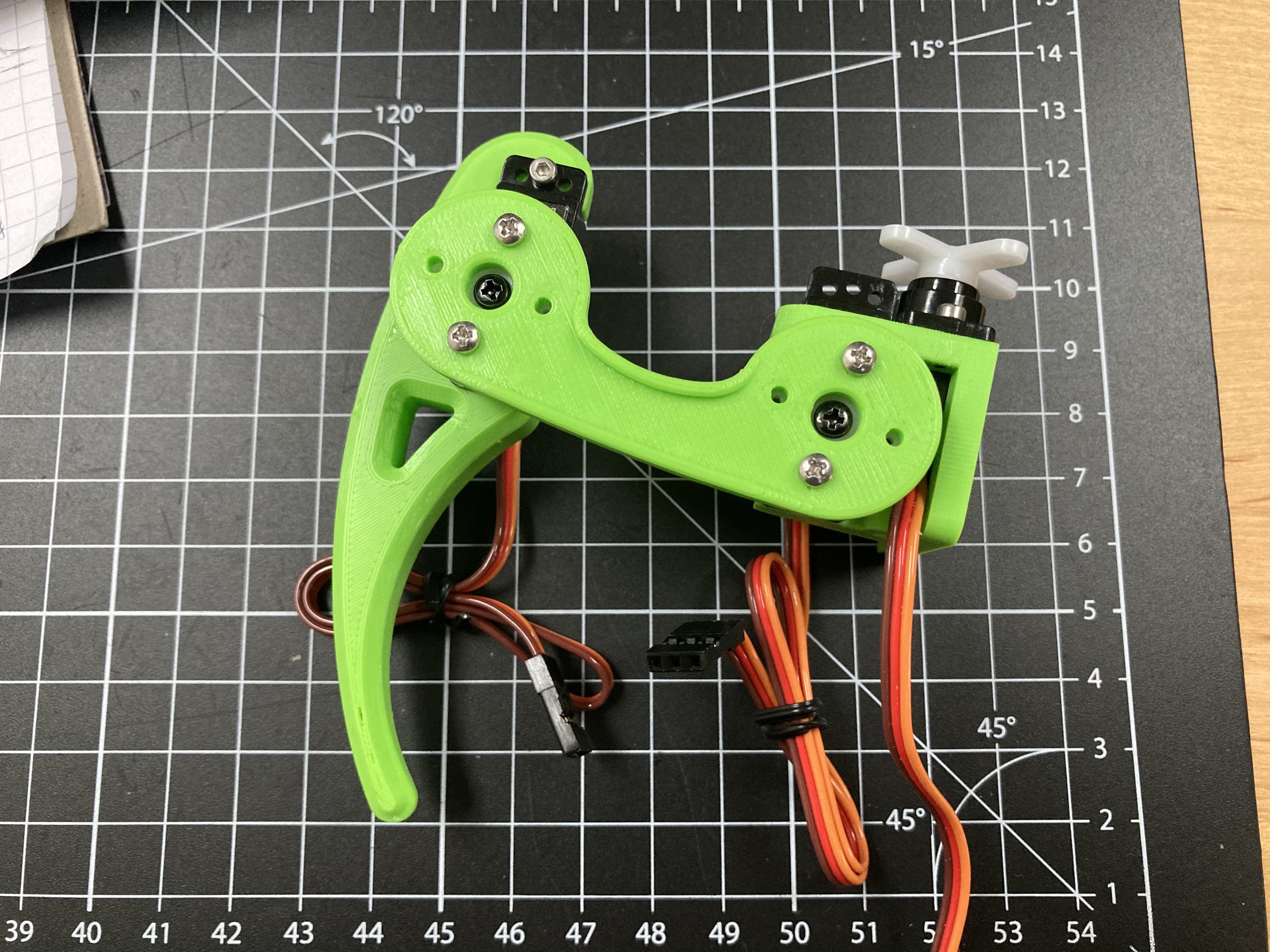
With the simulation done it was time to move on to the physical hexapod robot. I started designing parts for a single leg and searched for fitting servo motors. Since there are 18 servos needed for this hexapod, they define the total cost of the robot. I settled for some cheap Emax ES08A II micro servos. They are quite powerful for their size and their plastic gears seem to be holding up well so far. I paid around 80€ for the entire set of servos. When using proper smart servos for robotics, a single unit can cost this much.
Although they are “micro”, these servos can draw a lot of current. I was planning to use a lithium battery first but later switched to NIMH. The huge advantage is that six 1.2V NIMH cells add up nicely to 6V which the servos need. A lithium battery requires a voltage regulator, and with the high current demand that just complicates the project unnecessarily.
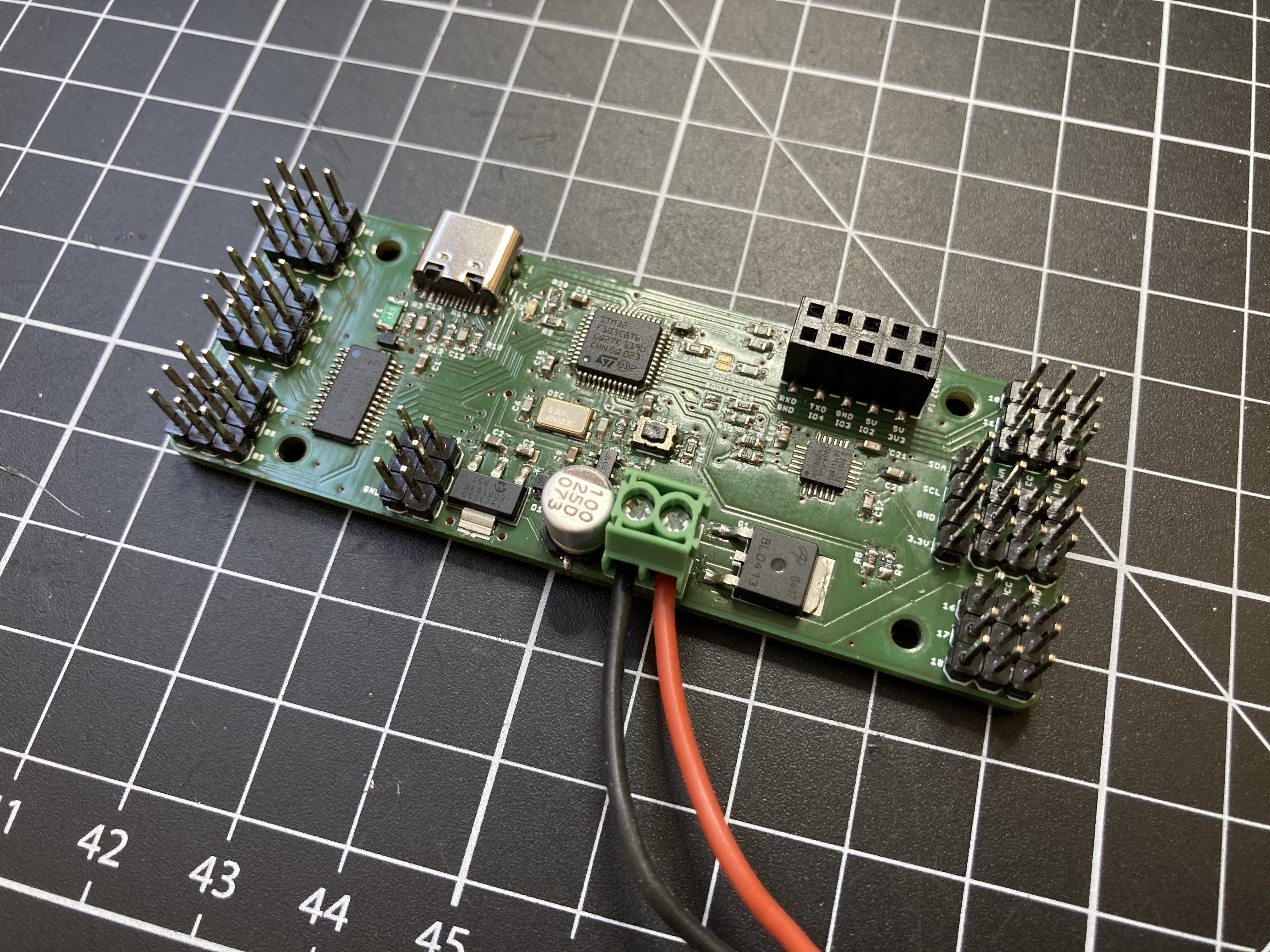
To drive the servos 18 PWM outputs are needed. At first, I tried to find a microcontroller with enough IO to connect the servos directly. The Teensy 4.0 might have been a good candidate for this. However, the robot has very limited space for electronics and the Teensy board just didn’t seem to fit right. The STM32F103 was the next best choice as it is Arduino-compatible and I had already gathered some experience with my macro keyboard. Because of the limited IO and timers, a PCA9685 PWM driver is used to control 16 servos while the remaining four can be handled by the STM32 itself. You can view the hexapod software running on a macro keyboard prototype below:
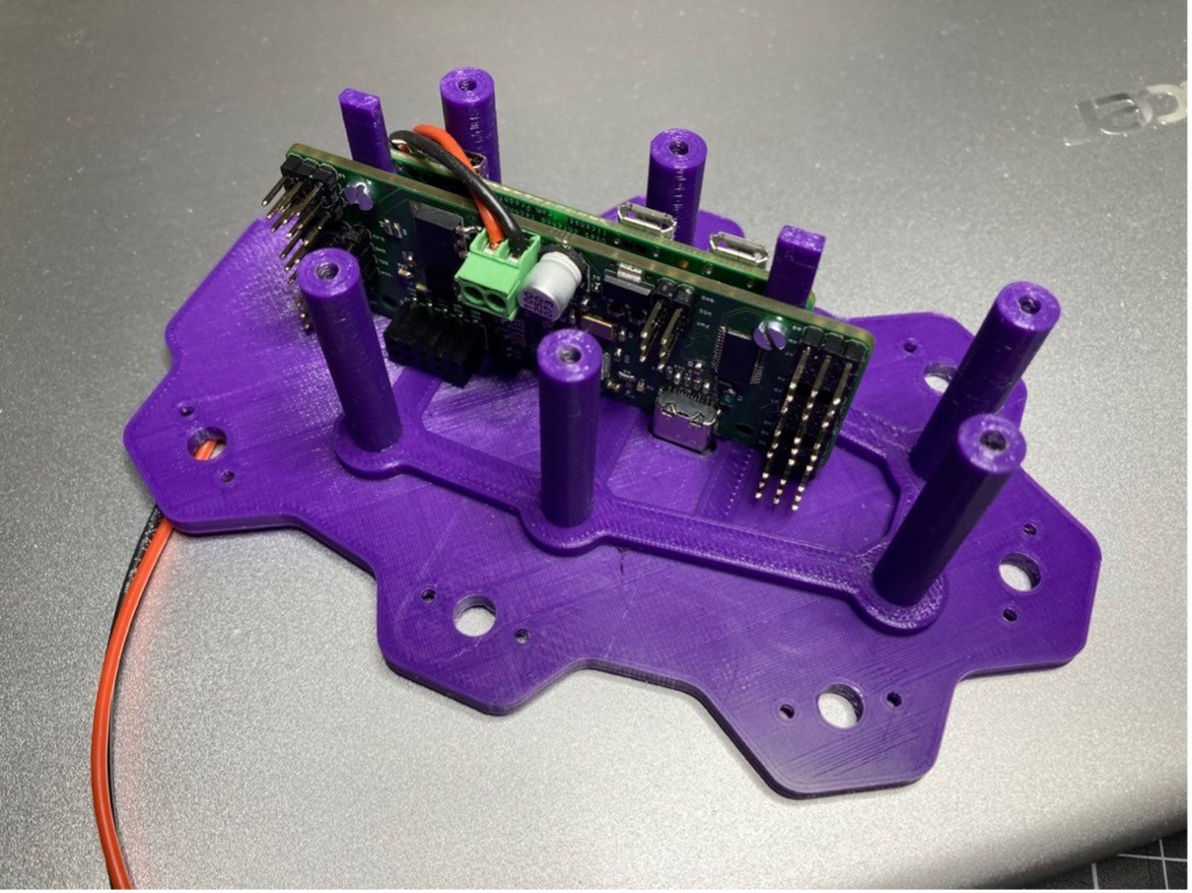
With the microcontroller selected, the robot still has no way to be controlled from the outside. To add wireless connectivity, I decided to include a Raspberry Pi Zero W. For my Pi Zero-based Zerobot robot I had already created software for a web interface, and I figured that adding a Bluetooth game controller should not be a problem. With the most important parts selected, I went on to create the PCB.
On the ZeroBug board, the microcontroller and Raspberry Pi are connected via UART. I am using a bottom-entry pin header. This allows for a very compact assembly without having to solder the Raspberry Pi. The STM32 can be programmed using its USB interface, while the Raspberry Pi is using its WIFI connection for access via SSH or VNC Viewer.
Supplying the components with power was tricky, as I wanted to be able to supply the board with either a USB connection or the battery. This is done by creating a diode-OR circuit (see picture below): With only USB attached, the Pi supplied with (almost) 5V, which it internally drops to 3.3V anyway. Additionally, the STM32 gets its own 3.3V regulator. When the battery is connected, it powers the servos directly through a simple reverse polarity protection. An additional 5V LDO supplies the Raspberry Pi and microcontroller. In reality this worked out great. Only with a very low battery, the Raspberry Pi might reset during quick movements. For this reason I am measuring the battery voltage with the STM32.

When orienting the parts some aspects had to be considered: The USB socket must be easily accessible. The servo connectors had to be positioned to minimize wire lengths. To get the Raspberry Pi’s antenna out of the way of motors and the battery, I had to point it towards the ground. Finally, the camera connector is oriented to the front of the robot so a camera can be attached later. I overlooked how long the pin headers for the servos are and together with the servo plugs they are too big to fit into the robot. Because of that the servo cables had to be soldered on later.
I managed to fit all the components on two-layer board. There was even space left for a MPU6050 motion sensor and a connector for I2C OLED displays. The connector came in handy for testing as an OLED screen can show the state of the legs without having to power the servos.
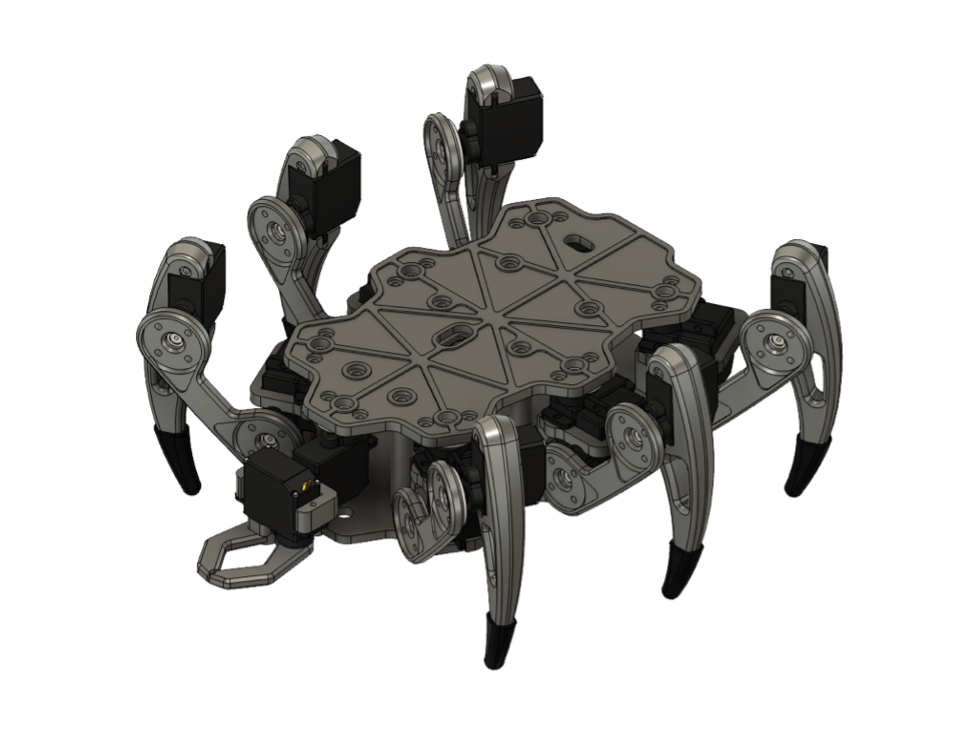
While I was waiting for the PCBs to arrive, I continued to design the 3D printed parts for the legs and body of the hexapod. I took the proportions of Matt Dentons uBug as a starting point. It turned out that I could barely shave off a few millimeters without compromising on the movement range of the legs. All the mechanical parts were designed in Fusion360 and can printed with minimal supports. To prevent slipping, I made some flexible TPU socks that can be snapped to the legs. I also added an optional claw to the front of the robot. This space was originally intended for a camera, but moving object with the claw it much more fun than a shaky camera stream.
Discussions
Become a Hackaday.io Member
Create an account to leave a comment. Already have an account? Log In.