Subhajit
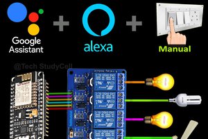
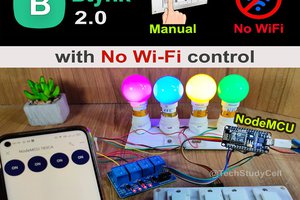
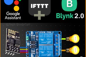
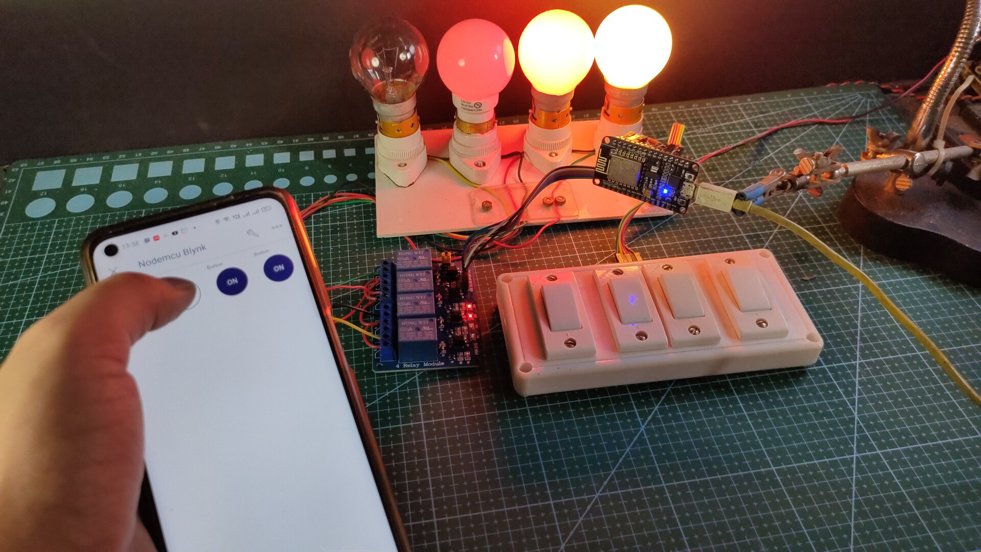
In this IoT project, I have shown how to make IoT-based Smart Home Automation using the new Blynk 2.0 & NodeMCU ESP8266 to control a 4-channel relay module from the manual switch & smartphone using the Blynk IoT App.
During the article, I have shown all the steps to make this Blynk home automation system.
Tutorial Video on new Blynk ESP8266 Smart Home:
This Blynk ESP8266 control smart relay has the following features:
- Control home appliances with WiFi (Blynk IoT App).
- Control home appliances with Blynk web dashboard.
- Control home appliances with manual switches or push buttons.
- Monitor real-time feedback in the Blynk IoT App.
So, you can easily make this home automation project at home just by using a NodeMCU and relay module. Or you can also use a custom-designed PCB for this project.
Required Components:
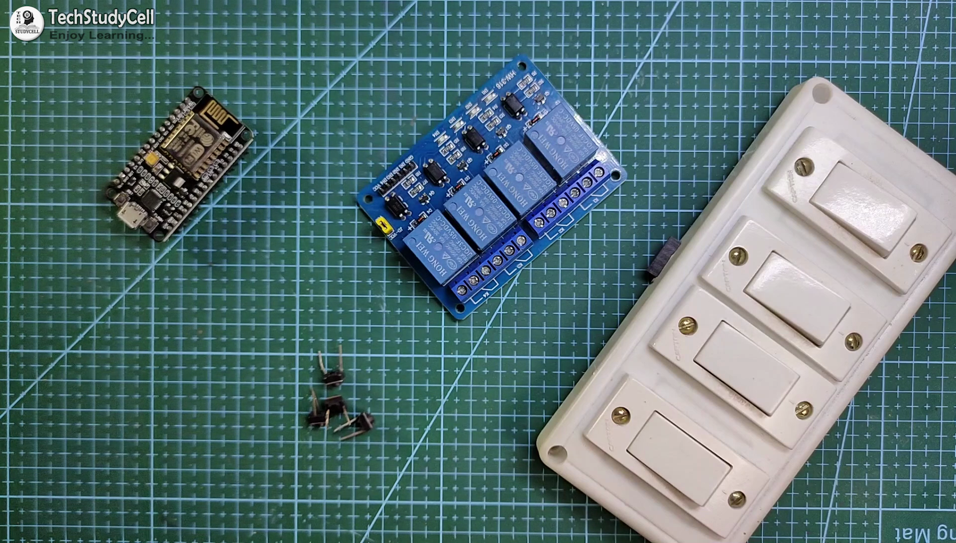
- NodeMCU board
- 4-channel SPDT 5V Relay Module
- Push Buttons or Switch
You can make this project just by using NodeMCU and 4-channel relay module. But if you use PCB then you need the following components.
Required Components for the PCB:
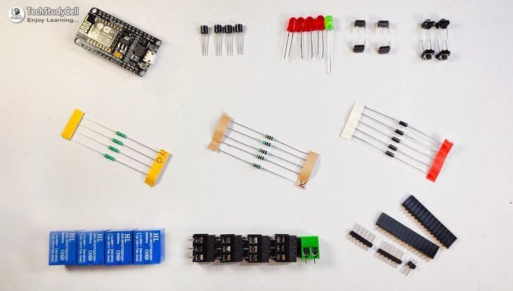
1. Relays 5v (SPDT) (4 no)
2. BC547 Transistors (4 no)
3. PC817 Optocuplors (4 no)
4. 510-ohm 0.25-watt Resistor (4 no) (R1 - R4)
5. 1k 0.25-watt Resistors (5 no) (R5 - R9)
6. LED 5-mm (5 no)
7. 1N4007 Diodes (5 no) (D1 - D5)
8. Push Buttons (4 no)
9. Terminal Connectors
10. 5V DC supply
Required Software:
1. Blynk IoT (Blynk 2.0)
2. Arduino IDE
Circuit Diagram of the NodeMCU Home Automation Project:
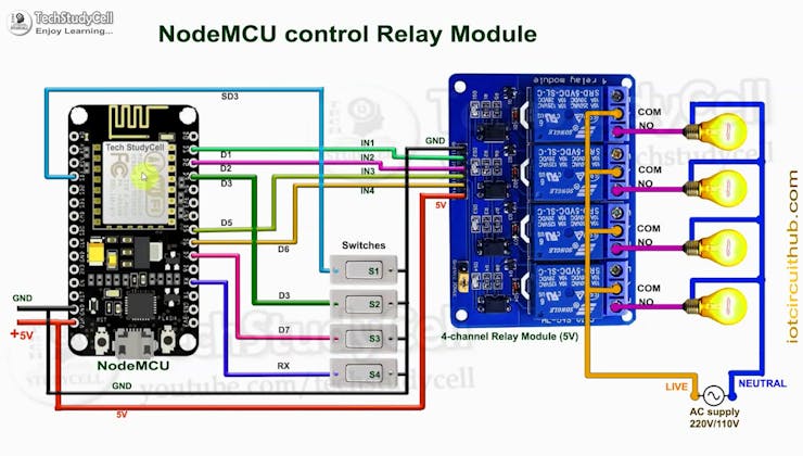
This is the complete circuit diagram for this home automation project. I have explained the circuit in the tutorial video.
The circuit is very simple, I have used the GPIO pins D1, D2, D5 & D6 to control the 4 relays.
And the GPIO pins SD3, D3, D7 & RX connected with switch or push buttons to control the 4 relays manually.
I have used the INPUT_PULLUP function in Arduino IDE instead of using the pull-up resistors.
I have used a 5V mobile charger to supply the smart relay module.
Here, the D3 pin should not be connected with GND during the booting process of NodeMCU.
Control Relays With Blynk IoT App:

If the NodeMCU is connected with WiFi, then you can control the home appliances from Blynk IoT App.
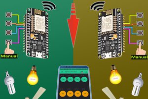
You also use multiple smartphones to control the appliances with Blynk App. For that, you have to log in same Blynk account from all the smartphones.
In this way, all smartphones will be sink to the Blynk server. You can control, monitor the real-time status of the relays from anywhere in the world with the Blynk IoT App.
Control Relays Manually With Switches:

You can also control the relays from the switches or pushbuttons.
You can monitor the real-time feedback in the Blynk IoT App.
Please refer to the circuit diagram to connect the pushbuttons or switches.
Design the PCB for This Smart Home System:

To make the circuit compact and give a professional look, I have designed the PCB after testing all the features of the smart relay module.
You can download the PCB Gerber file of this home automation project from the following link:
https://drive.google.com/uc?export=download&id=1Jx4D_DSV_ei1y0a82AbtxbsNhy8sjCmY
Order the PCB:

After downloading the Garber file you can easily order the PCB
1. Visit https://jlcpcb.com/RHS and Sign in / Sign up
2. Click on the QUOTE NOW button.

3. Click on the "Add your Gerber file" button. Then browse and select the Gerber file you have downloaded.
Uploading the Gerber File and Set the Parameters:

4. Set the required parameter like Quantity, PCB masking color, etc.
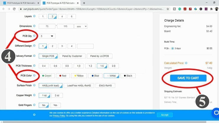
5. After selecting all the Parameters for PCB click on SAVE TO CART button.
Select Shipping Address and Payment Mode:

6. Type the Shipping Address.
7. Select the Shipping Method suitable for you.
8. Submit the order and proceed with the payment....
Read more »