 Petar Crnjak
Good read about this topic and where i pulled most of the data: https://www.st.com/resource/en/application_note/an5423-current-sensing-in-bldc-motor-application-stmicroelectronics.pdf
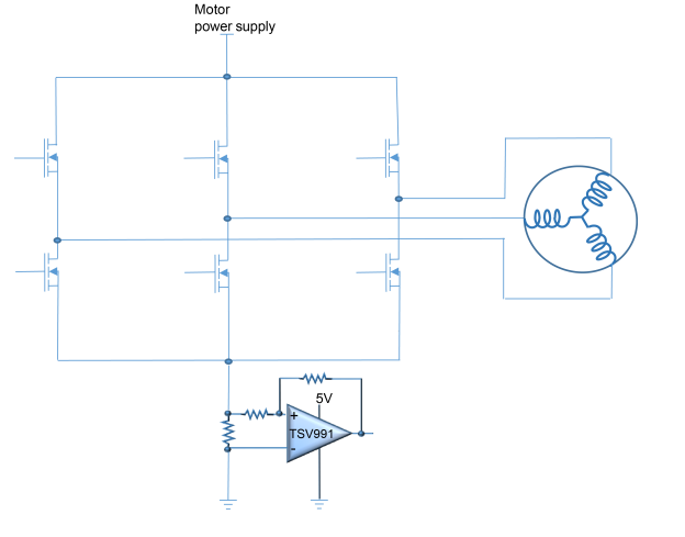
In this project, I used the simplest current sensing method and that is low side global current sensing. It is cheapest but generally used when you need to detect faults or some current limits. Not really good for torque control. Not really use din FOC
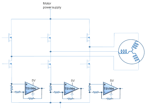
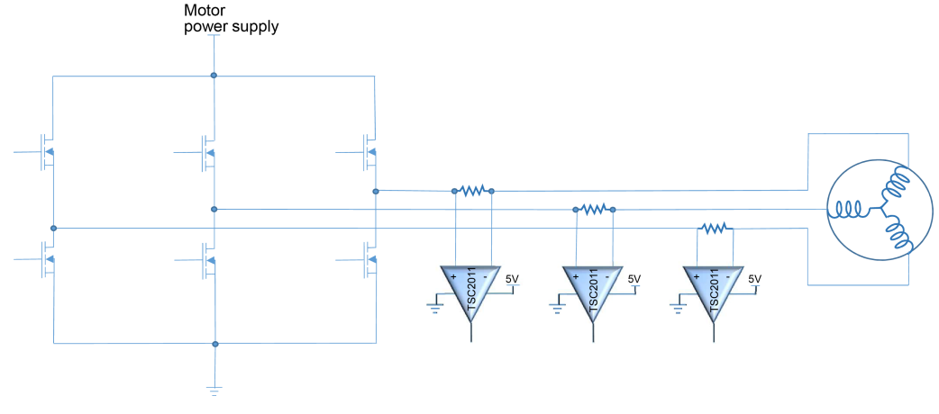
Here are the methods I will use in the next iteration.
The low-side configuration allows the use of a low-power op-amp as the common mode is close to the ground. This topology is largely used in FOC. The third current measurement branch is optional and can be calculated in the controller. The limitation is that low-side current sensing can only be executed while the low-side transistor of that leg is on.
This current measurement offers the best information that can be used in feedback motor control, in order to optimize motor performance. As the shunt resistance is placed directly in line with the PWM driver, it uses dedicated current sensing, which rejects the fast common mode variation. The main advantage of this topology is that the current can be read without a strong linkage to the PWM status and without timing limitations in the case of very small PWM applied to the phase.
Discussions
Become a Hackaday.io Member
Create an account to leave a comment. Already have an account? Log In.