 Petar Crnjak
In S-drive controller I used a 10-bit encoder. The encoder is connected to the output shaft of the BLDC motor. There is no encoder on the output shaft after the reducer. That means that one revolution of BLDC is equal to 1024 ticks of the encoder. One mechanical revolution of the motor relates to electrical resolutions by a number of pole pairs. For example, here I will use a motor with 11 pole pairs (22 poles). Now when we know the number of pole pairs of our motor we generate a sine table or space vector table that has a number of sine waves * number of pole pairs and fit it in an array of 1024 elements ( equal to our encoder resolution ). Link to the generator for that table (Matlab), (Python)
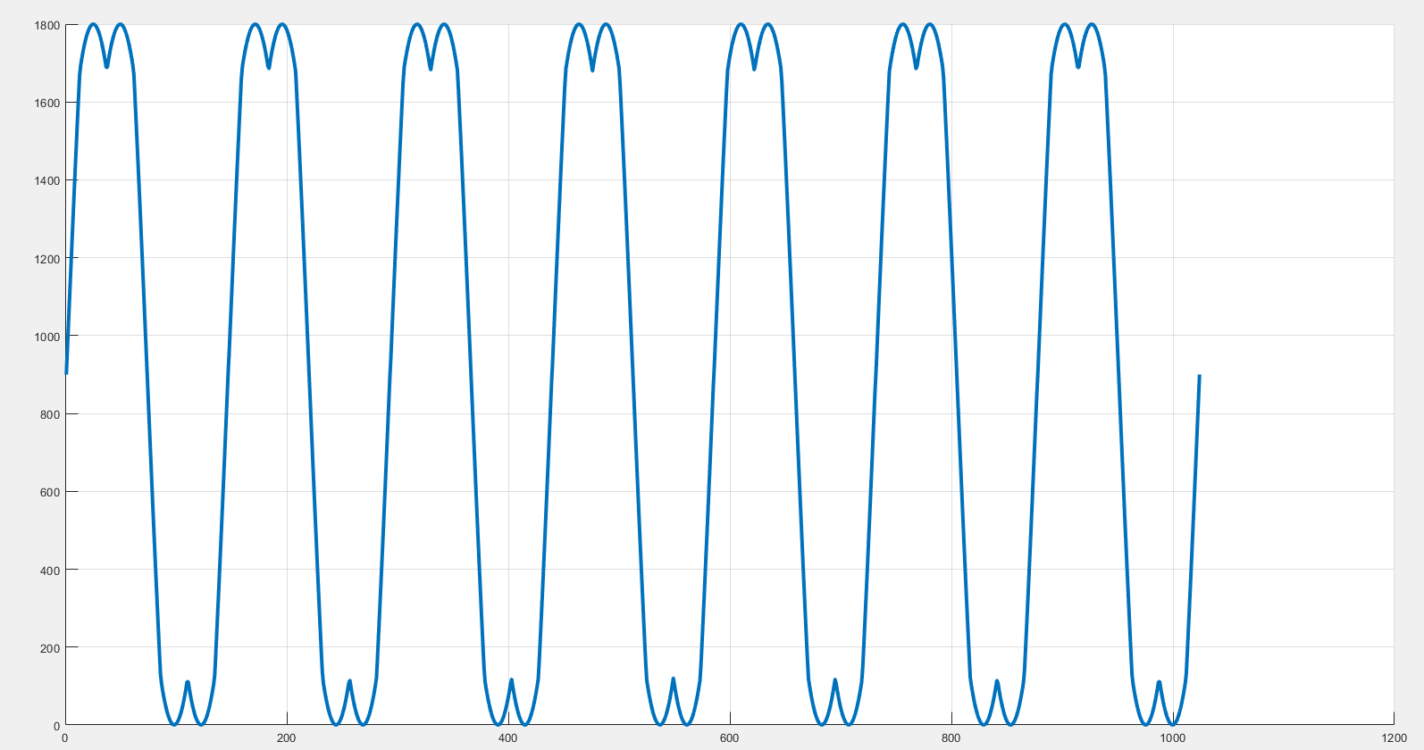
**This image is for 7 pole pair motor**
Max amplitude value of those sine and space vectors will be equal to the max duty cycle of our PWM module (it usually depends on the frequency we are switching our pwns) In my example, we are using 40khz switching and we have a max duty range of 0-1800 ( 0 – 100% duty cycle).
We can then adjust our sines amplitude by just dividing values in our table by some constant.
Now we need to create 90 deg magnetic field between the robot and stator. To do that we first align the rotor field to the stator by applying PWM on all the phases from sine table and offsetting them by 120 deg. For example, we have 11 pole pair motors. One period of the sine wave will be represented by 1024/11 = 93 elements of the array. Now to align the motor we will apply the value of sine table[0] to phase 1. For phase 2 we will apply sinetable[0] + 120 deg offset. If 93 represents 360 deg; 120 deg = 93 / 3 = 31 so value of phase 2 will always be offset for + 31 from phase 1. That means that phase 3 will be offset from phase 2 for 31, or for 62 from phase 1. After we did this alignment rotor and stator fields will have 0 deg between them, They will be locked in position. Now we tell our encoder that this current position is equal to 0. After that, We map encoder ticks to the sine table but with an extra 90 deg offset ( 90 deg is equal to 93 / 4 = 22)!! So for example for encoder position 0 we would use element value sinetable[encoder_tick + 0 deg offset + 90 deg offset] that would equal in our case sinetable[ 0 + 0 + 22] for phase 2 it would be sinetablae[ 0 + 31 + 22], for phase 3 it would be sinetablae[ 0 + 31 + 44] And that is it, Motor is now acting like DC motor where we can regulate speed by changing the amplitude of our sine waves (Dividing values from sine table by some value). All code is here.
Discussions
Become a Hackaday.io Member
Create an account to leave a comment. Already have an account? Log In.