What is a Boost Converter?
A boost converter (step-up converter) is a DC-to-DC power converter that steps up voltage (while stepping down current) from its input (supply) to its output (load). It is a class of switched-mode power supply (SMPS) containing at least two semiconductors (a diode and a transistor) and at least one energy storage element: a capacitor, inductor, or the two in combination. To reduce voltage ripple, filters made of capacitors (sometimes in combination with inductors) are normally here are only a few parts required to make a boost converter. It is less cumbersome than an AC transformer or inductor.

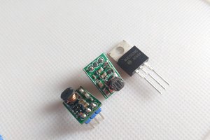
There are only a few parts required to make a boost converter. It is less cumbersome than an AC transformer or inductor.
They’re so simple because they were originally developed in the 1960s to power the electronics systems on aircraft. It was a requirement that these converters be as compact and as efficient as possible.
The biggest advantage boost converters offer is their high efficiency – some of them can even go up to 99%! In other words, 99% of the input energy is converted to useful output energy, only 1% is wasted.
Boost Converter Theory
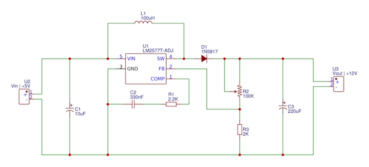
The input could up to 12 volts. Don't apply a higher voltage or you could burn the LM2577-ADJ component. In this case, we need no external switch since the LM2577-ADJ already has it inside it. With the feedback pin connected to the output voltage divider, the LM2577-ADJ will change the width of the pulse depending on the output in order to keep it constant. In this case, use a Schottky Barrier Rectifier diode because it has a low forward voltage. This diode will live the current flow when the switch is open.
In order to study how it works, we will divide it into two states.
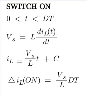
The ON and OFF states. In the ON part, the switch is closed as we can see in the next figure where the diode is open because the cathode voltage is higher than the anode. The key principle that drives the boost converter is the tendency of an inductor to resist changes in current by creating and destroying a magnetic field. In a boost converter, the output voltage is always higher than the input voltage. When the switch is closed, current flows through the inductor in the clockwise direction, and the inductor stores some energy by generating a magnetic field. The polarity of the left side of the inductor is positive. So in this case we obtain the current through the inductor using the next formulas.
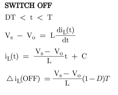
When the switch is opened, the current will be reduced as the impedance is higher. The magnetic field previously created will be destroyed to maintain the current towards the load. Thus the polarity will be reversed (means left side of inductor will be negative now). As a result, two sources will be in series causing a higher voltage to charge the capacitor through the diode D.
In this case, the voltage across the inductor is the difference between the output voltage and the input. So once again using the next figure formulas we obtain the current of the OFF part depending on the duty cycle.
Ok, now if we want to obtain the output depending on the input and the duty cycle of the PWM all we have to do is to make the sum of the On and Off current equal to 0. That means that the On current is equal to the Off current. So that will give us:
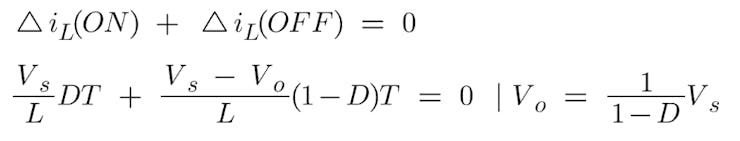
So we've obtained that the output is dependent on the duty cycle disproportionate. So the bigger the Duty cycle gets, the higher will be the output. The duty cycle of the PWM can have values between 0 and 1. So the only possible output will be equal to or higher than the input. That's why this configuration is called a step-up converter.
Booster Converter using LM2577-ADJ circuit
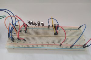
With this component we have feedback and the output will stay the same using different loads. Just make the connections, add the input capacitor to have a steady input and you're done.
The input could up to 12 volts....
Read more »
 hesam.moshiri
 w_k_fay