 josh collins
Anyone who has worked with servos knows that it is difficult to achieve natural movement. They are built to give a constant velocity and torque which results in jerky movements. To combat this, there needs to be some passivity built into the design. Some robots use springs, but that means that the passivity cannot be adjusted. More expensive designs use a rotary passive actuator based on large geared down DC motors. However, they are bulky, have many parts, and the price range is greater than most people can justify.
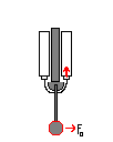
Desired motion:
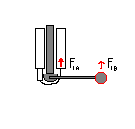
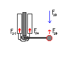
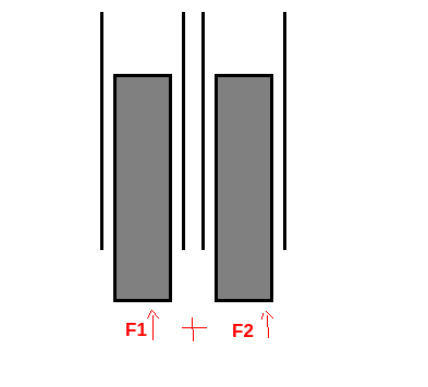
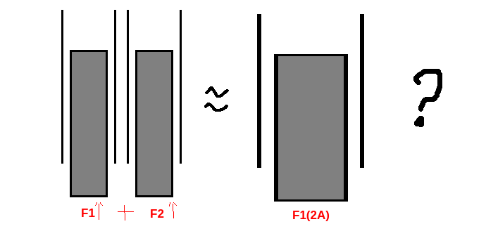
Most biological muscle only contracts when energy is applied, and remains passive all other times. Because of this, there are typically two opposing muscles: flexors and extensors. A holding force can be achieved when the right amount of energy is put into the two opposing muscles. My first design uses one pwm signal per flexor or extensor to achieve a similar mechanism.
Wont that cause inaccurate movement?
Yes. That is the point actually. Modern robots need to handle unpredictable movement. AI is at the point where it pairs well with manipulators that need to be adjusted on the fly. Robots are learning to learn on their own so we no longer have to hand code walking gates.
 Kārlis
 DeepSOIC
 peter jansen
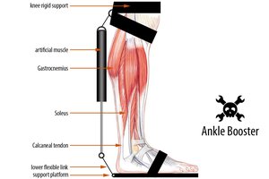
 Radu Motisan