 Jan
JanTL;DR
I wanted a way to build a wireless Macropad which lasts for months on preferably two AA or AAA batteries. I'm already using a wireless Logitech keyboard and mouse, so building something using an existing receiver made sense to me...
How
- bought a semi-broken Logitech K400 TV wireless keyboard for 5€ and threw everything away except the circuit board.
- removed the graphite layer on the PCB (where the two keyboard sheets with their silver conductive painted traces connects to the board)
- soldered 21 thin leads to the board which fan out to a breadboard-friendly pin-header
- find the right connections for the key-presses you want to have on your Macropad. Using resistance-mode on the meter helps a lot.
That's it?
Not quite. There's a few pitfalls:
- without re-programming the chip you are restricted to simple keystrokes. Multi-key pressing is possible, we'll get to that soon
- the chip is polling through the rows/columns, which are on pins 1 to 10 and pins 11 to 21 respectively. We need to add a simple circuit to do a multi-key press
- timing / order of key-presses must be considered. Pressing e.g. CTRL+ALT+DEL exactly at the same time does confuse the controller and isn't recognized as the keystroke by Windows
How to do a single button press
It's easy: just find the two pins which connect to the key you want to press. Examples:
- SHIFT: connect 1+11
- CTRL: connect 2+12
- ALT: connect 9+21
- (...)
Connection between the two pins can be up to several hundred ohms but it can not be a Mosfet or transistor as this messes with the internal polling of the on-board chip.
How to do a multi-key-press
Glad you asked! For my Macropad I want to use CTRL+ALT+SHIFT+F1 to F6 or maybe even F12. How?
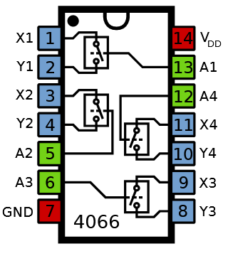
Solution: The venerable 74HC4066 Quad single-pole single-throw analog switch. Or even better: many of them :) Here's the pinout (Source: https://commons.wikimedia.org/wiki/File:4066_Pinout.svg):
So, let's say we want to press CTRL + X with a single press of a button. For that we connect:
| 4066 pins | Logitech board pins | Comments |
|---|---|---|
| 7 + 14 | GND and +3V | |
| 1 + 2 | 2 + 12 | |
| 3 + 4 | 1 + 15 | |
| 5 + 13 | hard-wired together. Add a momentary switch to +3V |
Now when we press the button, the two internal switches of the 4066 are closed and the Logitech PCB sends our keystrokes. Nice, eh? But the controller expects the modifier keys (CTRL, SHIFT, ALT) to be pressed ever so slightly before the other keys.
The venerable RC-delay
We use the fact, that when a voltage first is applied to a capacitor, the cap acts like a short. It slowly charges up to what you put in (say 3V). You can read up on it here.
We use that behaviour to activate some keys a few milliseconds after the modifier keys:
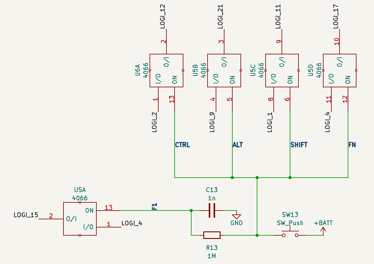 When the button is pressed, the 4 modifier keys are immediately activated. The F1 key is activated slightly after, because the cap first needs to charge through the 1M resistor.
 Finding the right values is a bit tricky here, as the charging capacitor "slowly" goes from 0V to 3V here. The 4066 switches gradually lower their resistance the higher the input (control) voltage is.
Here's an example of what the the Harris Semi (now TI) HC4066 accepts as LOW and HIGH at their inputs:
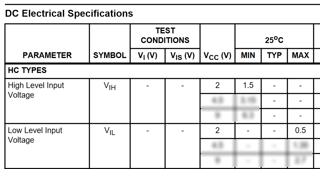 Assuming Vcc = 2V (in our case its 3V), we need to have a maximum of 0.5V on any input till the switch starts conducting. Then there's the forbidden area between 0.5 and 1.5V where the switch does this or than, it isn't specified nor guaranteed. Texas Instruments has very nice documentation on the topic!
 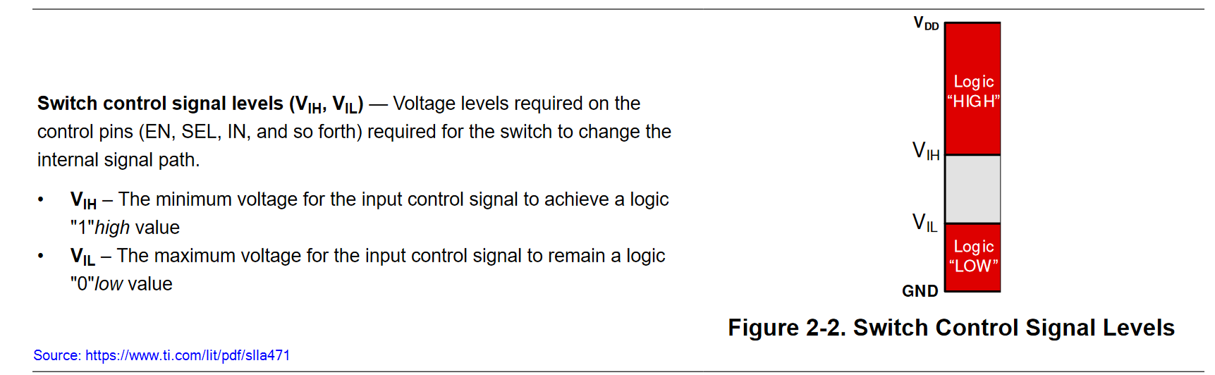 With a minimum of 1.5V the switch starts to act as "closed" = low resistance.
 Simon Merrett
 deʃhipu
 Pamungkas Sumasta