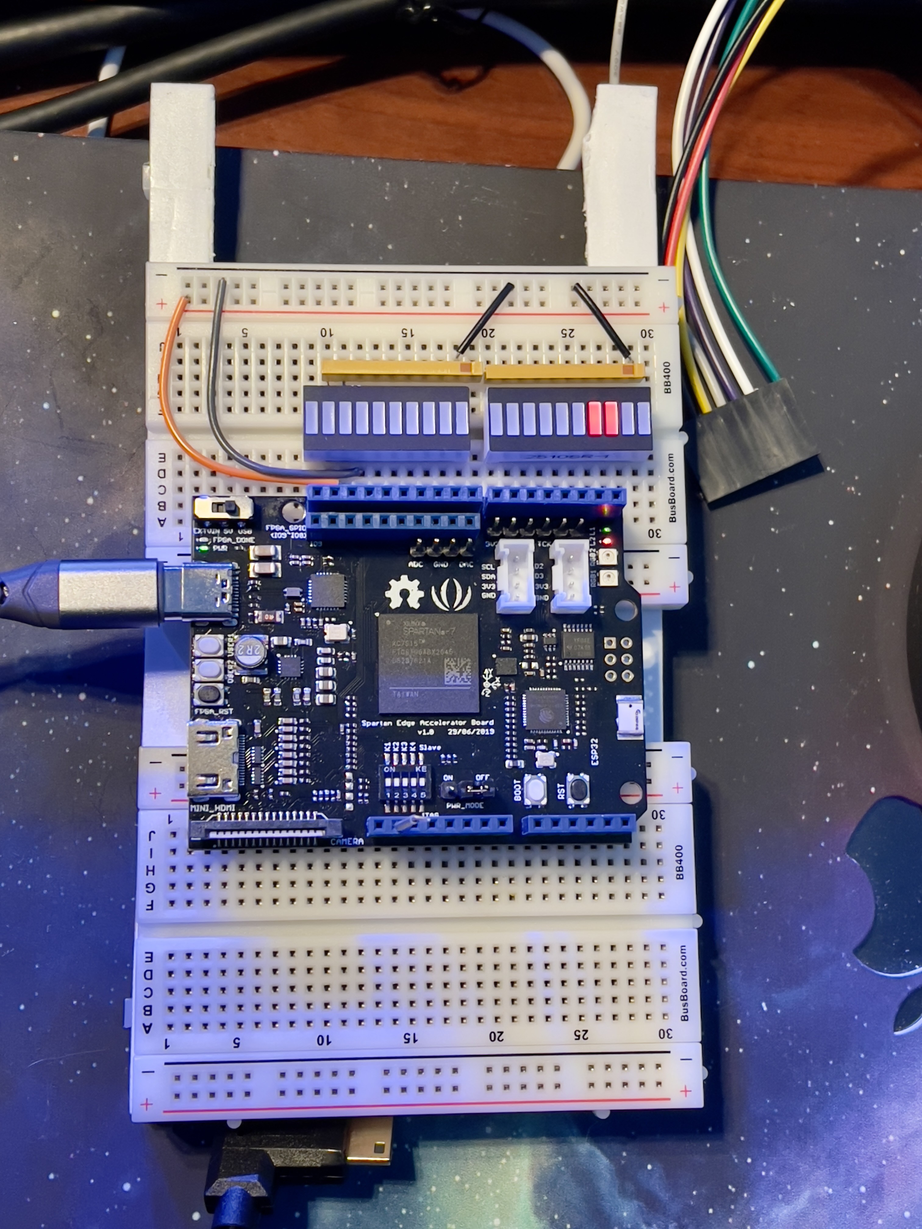
In preparation for ALU development on the FPGA, I decided to hook up all the external pins of the Spartan Edge board to LEDs and switches so I can do at least a bit of debugging. Ultimately, once I have more of a working CPU, I can likely interact through the ESP32, I2C, or something. But for now, it will be more hands-on. First, though, I had to solder on the headers for various connections (using my brand new digital microscope!), as the Spartan Edge leaves those off initially as verious user options to install as needed.

The Spartan Edge board has various connections to the Spartan-7 FPGA and the ESP32 onboard. Many of the IO pins from the Spartan-7 are laid out and configured with resistors to be used with an Arduino Uno, and a few are directly wired. We have 14 pins from the Arduino Digital IO headers, and 10 pins from the FPGA directly. Unfortunately, the Analog pins are instead wired directly to the ESP32, which is all fine, but since we're not using that right now it isn't helpful.
One very unhelpful note is that there are NO 3.3v pins at all (at least on any of these headers) to get VCC_3v3 from the board! I did some checking, and the ONLY place you can get regulated VCC_3v3 from the board is the two Grove connectors, which are intended to be used for I2C or whatever, and the JTAG connector which I need in order to program the FPGA. I didn't have any Grove connectors, so I'll need to wait for them to come in later this week. Unfortunately, the pins are too small to get female jumper wires to stay put.

For now, I can at least set up the breadboard with some LEDs and switches. My first attempt was to just place the board directly on two short breadboards, which would be way cleaner, however, I soon realized that all the pins I need are on one side of the board, and if I run jumper wires to the breadboard, I can't use the top row of connections if the board pins are connected. So, on to plan B...

Now I have the FPGA board plugged into the breadboard, mostly just to hold it in place, as I am not currently using any of the analog or signal pins from that bottom Arduino header. I then run ribbons of IO pins to the breadboard. Initially, I'm running the Arduino 0-13 pins as output driving the LEDs in sets of 8, 4, and 2, and the 10 FPGA pins to switches in 8 and 2. Here they are just tied to Ground, since I don't have the VCC side wired yet, so the switched inputs float when not grounded...resulting in noise, but I can at least see they are working.
There are also some switches, two pushbuttons, and a few LEDs on the board if I need those. I figure I can use the pushbuttons to step through test cases.
Next up, get some ALU functionality coded up on the FPGA so I can step through some logic on the test connections.
 Tom
Tom
Discussions
Become a Hackaday.io Member
Create an account to leave a comment. Already have an account? Log In.