0%
0%
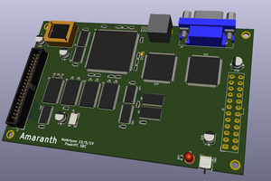
Resurrecting an old floppy drive with a new board!
That's it. That's the project. I'm trying to remanufacture a logic board using only the schematics from the manual.
 TheMajorTechie
Become a Hackaday.io member
Already have an account? Log in.
Just one more thing
To make the experience fit your profile, pick a username and tell us what interests you.
Pick an awesome username
hackaday.io/
Your profile's URL: hackaday.io/username. Max 25 alphanumeric characters.
Pick a few interests
Projects that share your interests
People that share your interests


 Carson Herrington
 Michael Rangen
 Kal
Kal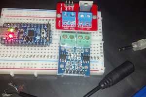
 Welsh Mullet
So far, it doesn't seem like it. Almost all of the parts listed on the schematic are either passive components or TTL chips. Though, it seems like the amplifier chips used for the read/write heads might be growing a little scarce.