 Jonathan
Intro:
last week I was working on a few different parts of MycoHub's hardware, as well as pushing the software along for the controlled environment.
- Added the ceiling / Raspberry Pi pan to the MycoBox and varnished it
- Modeled how the Laminar flow will fit on the MycoLab (above the Raspberry Pi pan)
- Created a prototype board to organize the sensors' and relays' wiring to the Raspberry Pi
- Switched the AC port with a much smaller one
1 ) Raspberry pi pan & the MycoBox ceiling
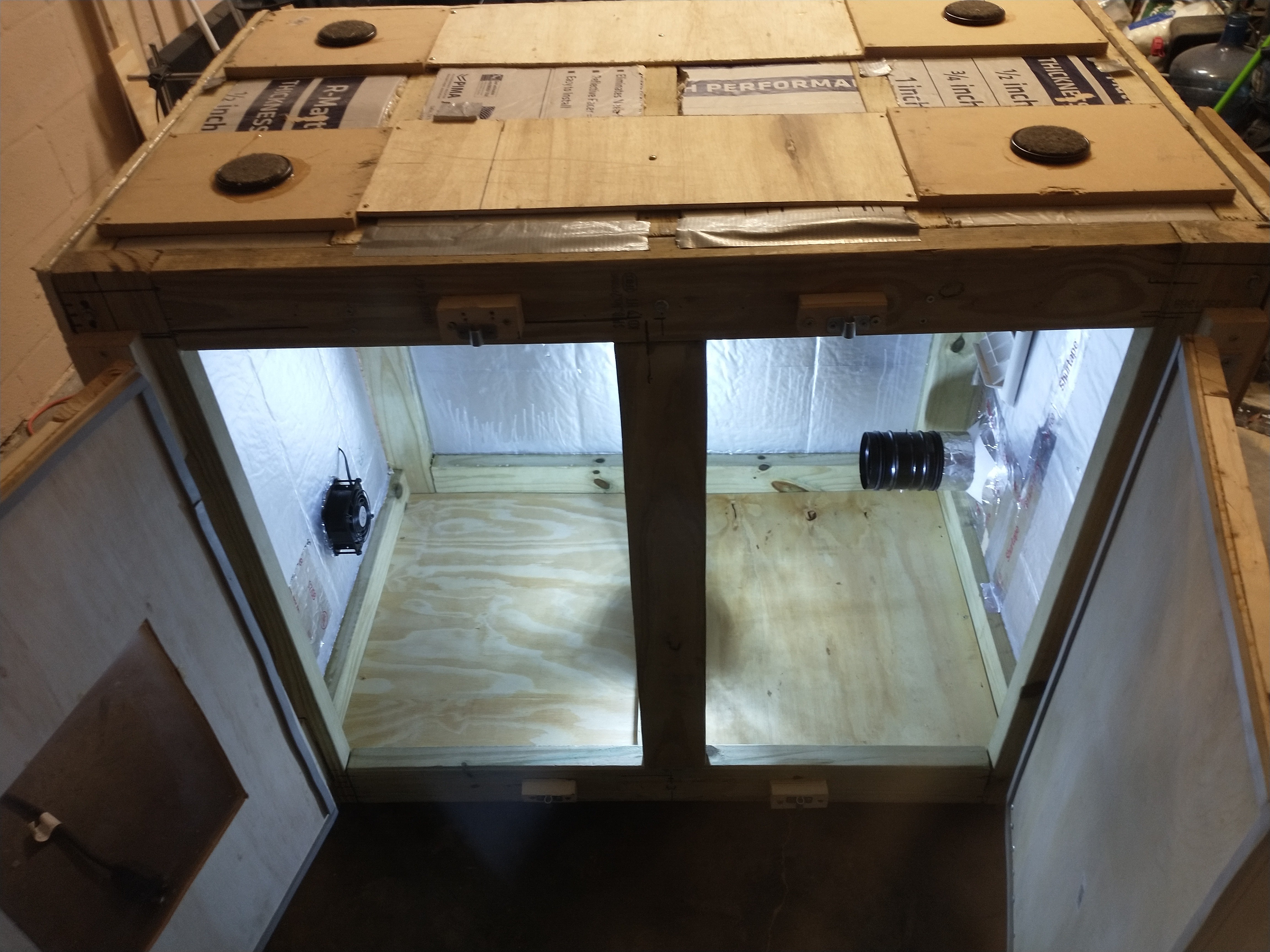
^ MycoBox flipped upside down to varnish the ceiling, all of the interior wood is double varnished
^ Raspberry Pi pan (MycoBox attic / MycoLab basement)
The Raspberry Pi is positioned in this 4.5" deep pan above the MycoBox. The sensors will drop into the MycoBox, the relay wires will come through a port on the left of the Raspberry Pi pan, and the wires from the fans on the right side of the box cross through this section to reach the relays on the left as well. This way all wiring is above the MycoBox and below the Mycolab, while the main power lines are kept safely in a junction box on the left side of the MycoBox.
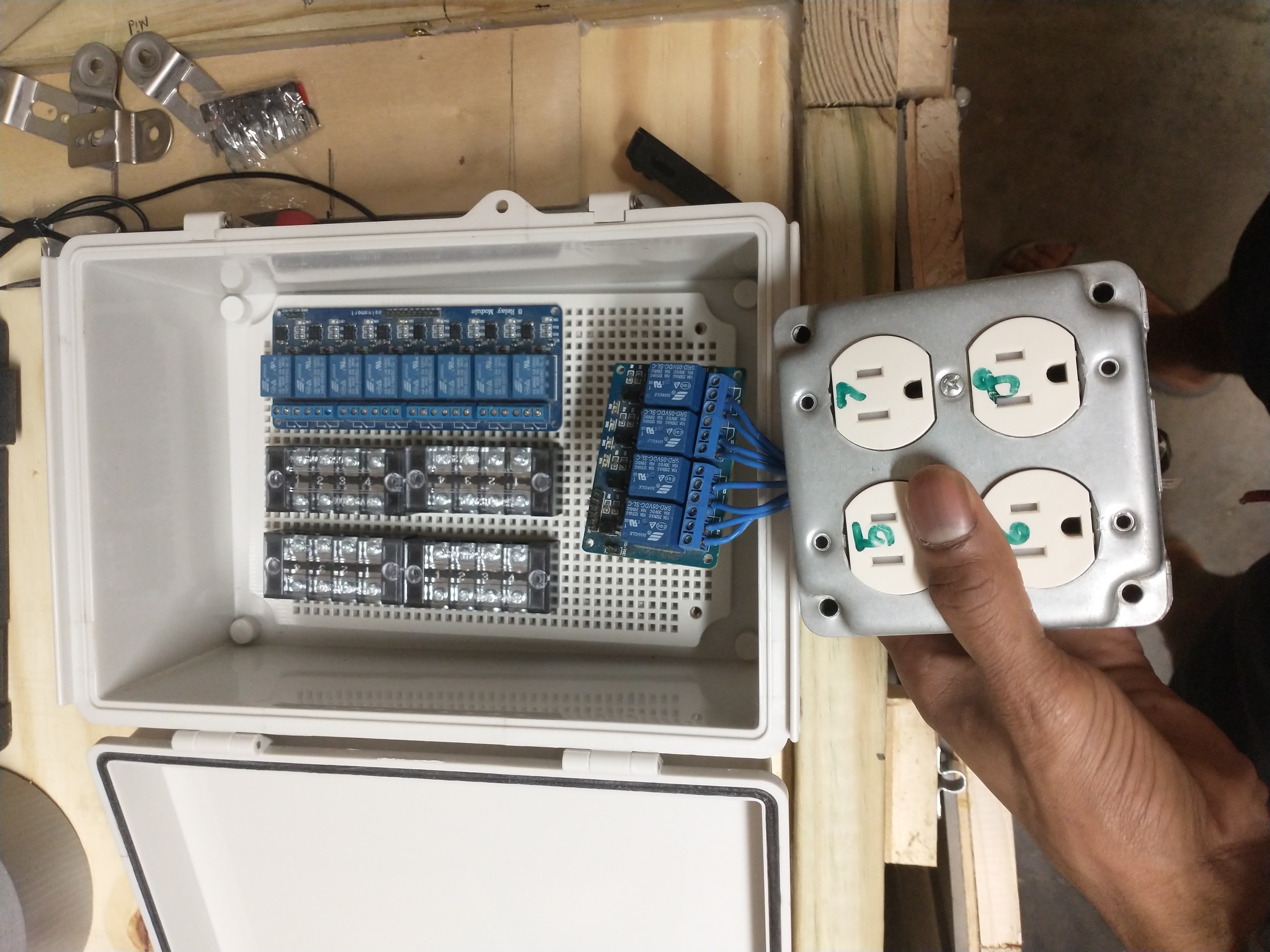
^ Junction box for the 2 relays. This is just showing how the relays will fit inside the box, I will actually assemble and mount this tomorrow.
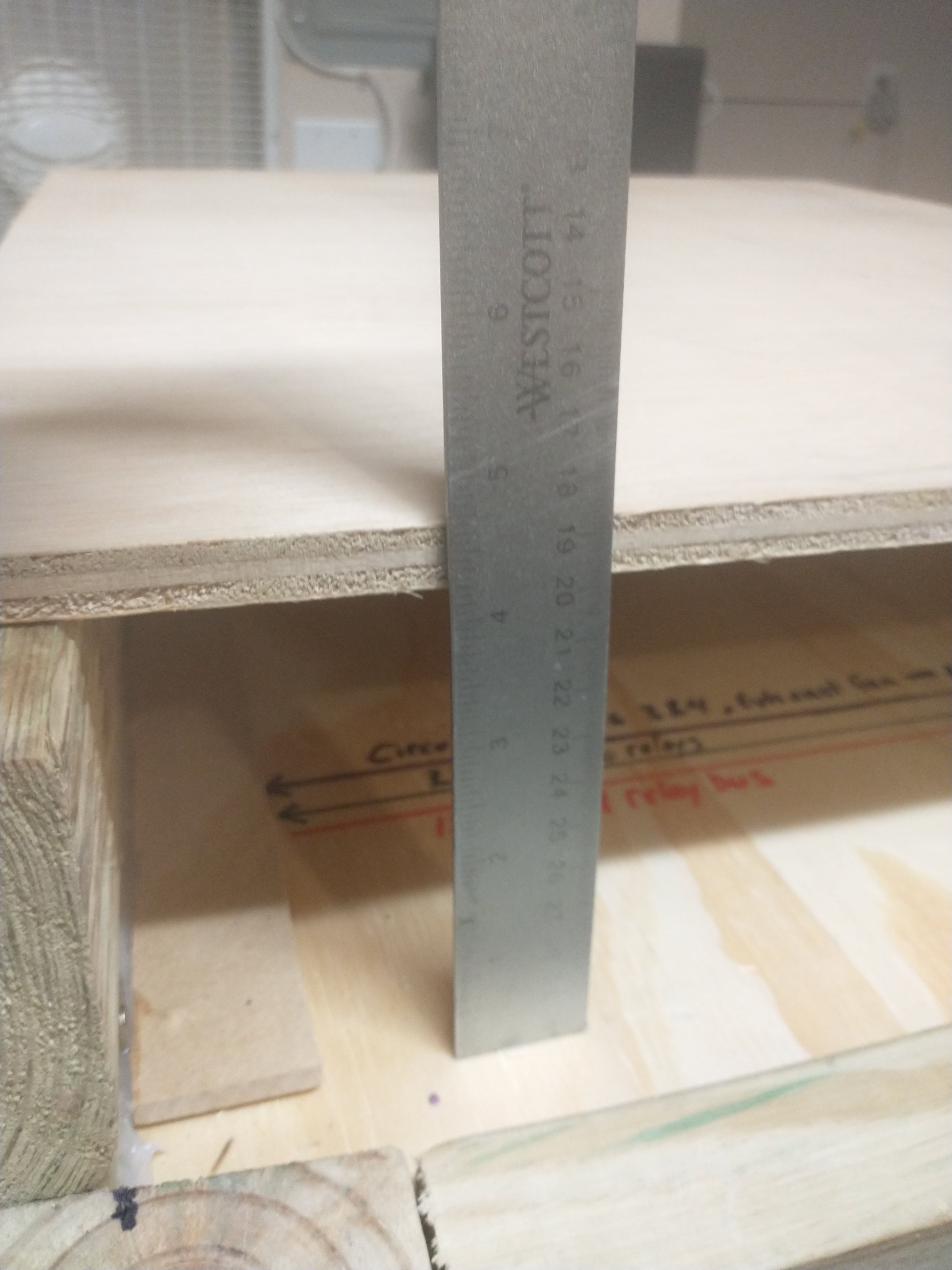
^ This 4.5" spacing, as mentioned in a previous post, gives enough room to add ventilation fans to the Raspberry Pi pan; which may not be necessary, but just incase things get hot after running the MycoBox for a 4 week fruiting session. It also raises the MycoLab to the perfect standing desk height for me, I'm 6'2".
2) 16" x 16" x 11.5" Laminar Flow
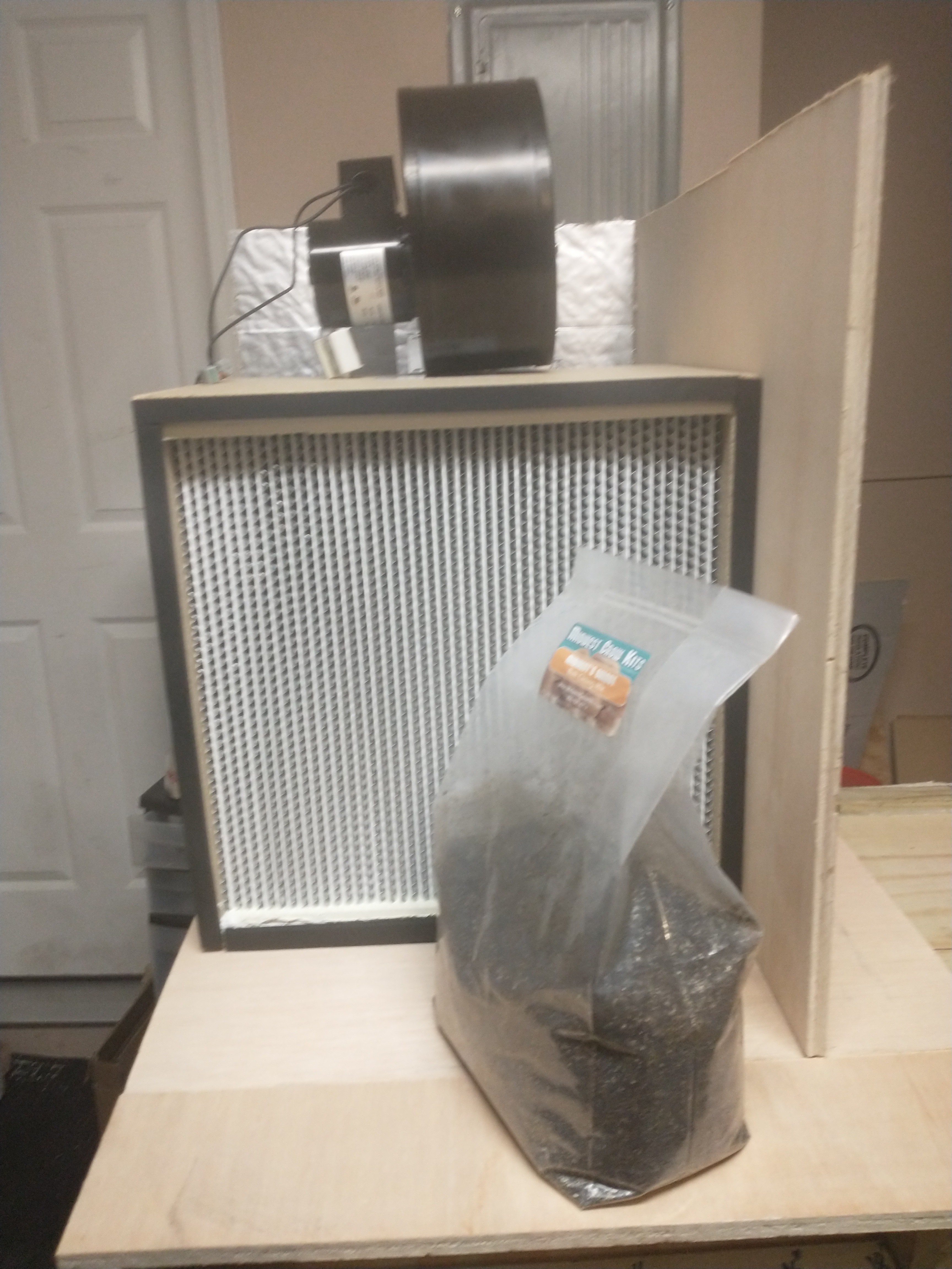
^ This is not constructed yet, just demonstrating the spacing and location of the laminar flow. The 16" wide filter gives enough room to inoculate grow bags comfortably, and it takes up less than half of the available table space. It's also of course very easy to start agar plates, or do any other lab work in front of this.
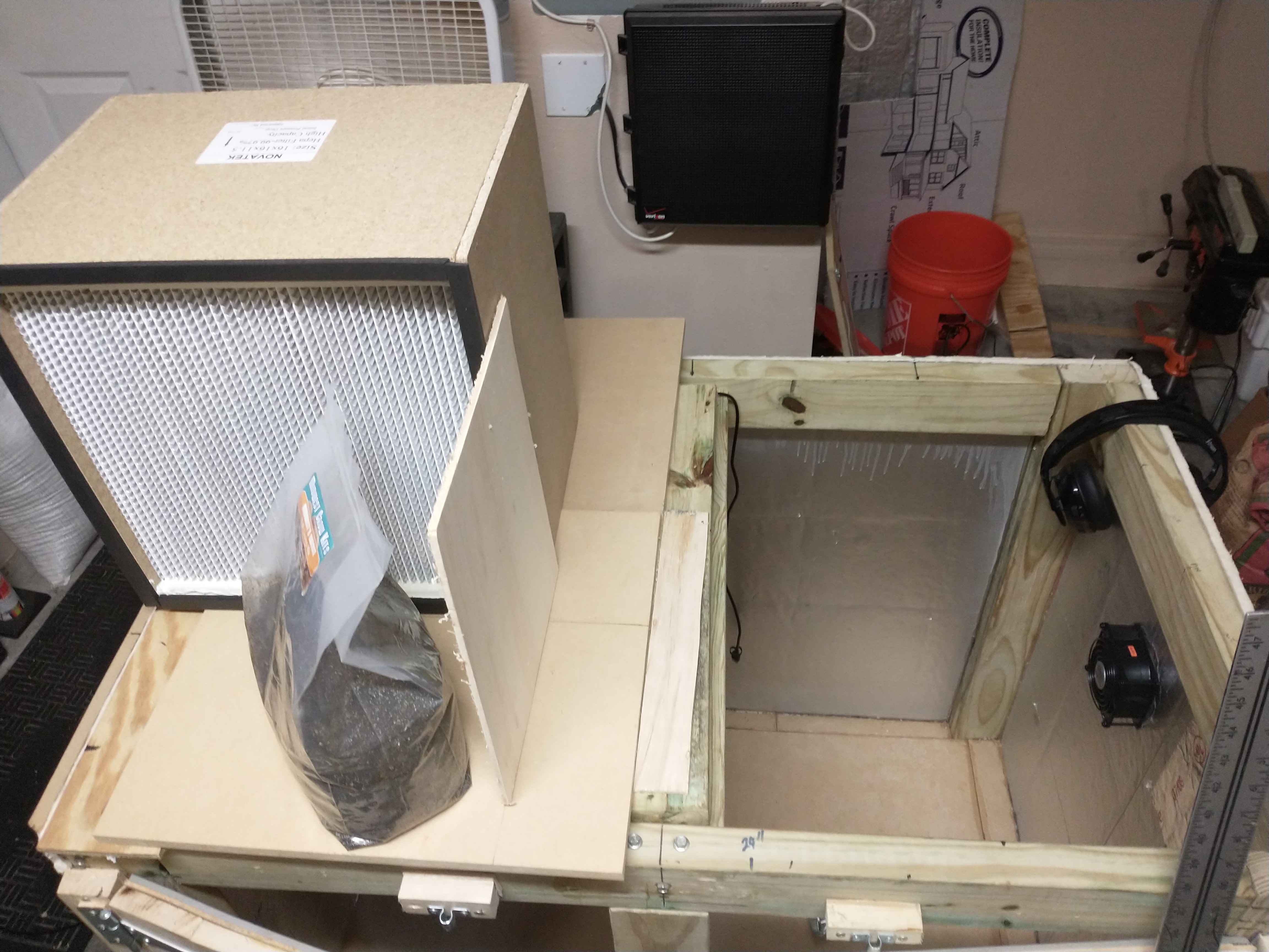
^ This is image is just showing the amount of space left available. I haven't added the remainder of the ridge that lifts the MycoLab above the MycoBox, and need to get another board for the base of the MycoLab; I accidentally did a terrible job sizing and cutting the board the first time.
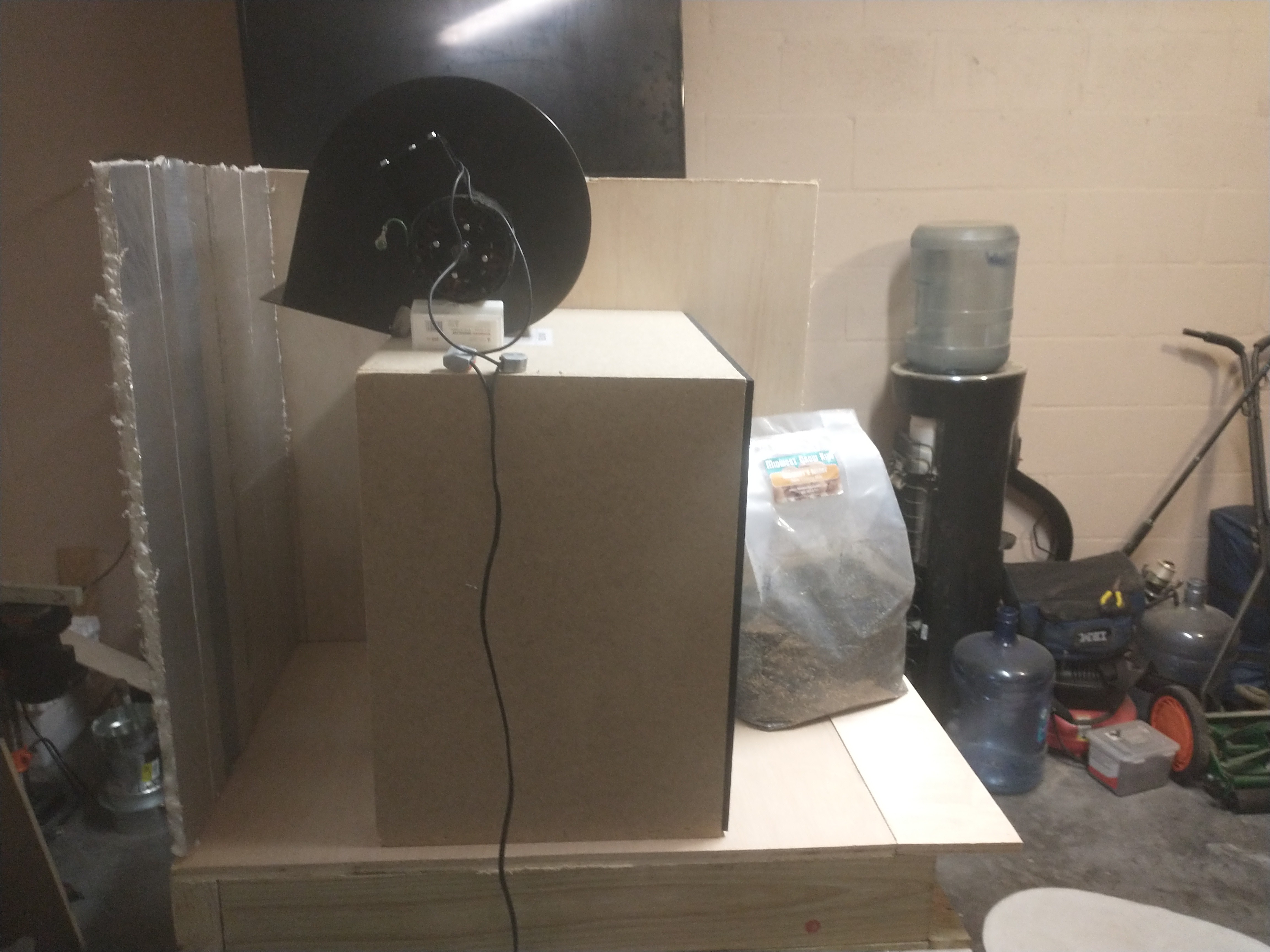
^ This is a 273 CFM centrifugal blower fan, which is enough to keep the air speed through the filter well above 100 fpm. I determined the minimum required fan speed by multiplying the 1.77 foot surface area of the filter by the 100ft/min rate air speed, which calculates to a 177CFM fan. The space behind the filter is 6" deep and will be a closed box that the fan mounts on top of. The fan itself will also be in a closed box with the only vent having a pre-filter on it, which is to keep larger particles from ever reaching the laminar flow filter. It will be built in a way that makes it easy to slide the filter out for replacement when the time comes. This is pretty much the only hardware that won't be connected to the raspberry pi, there will simply be a switch for turning the fan on or off.
3) Raspberry Pi Prototype Board
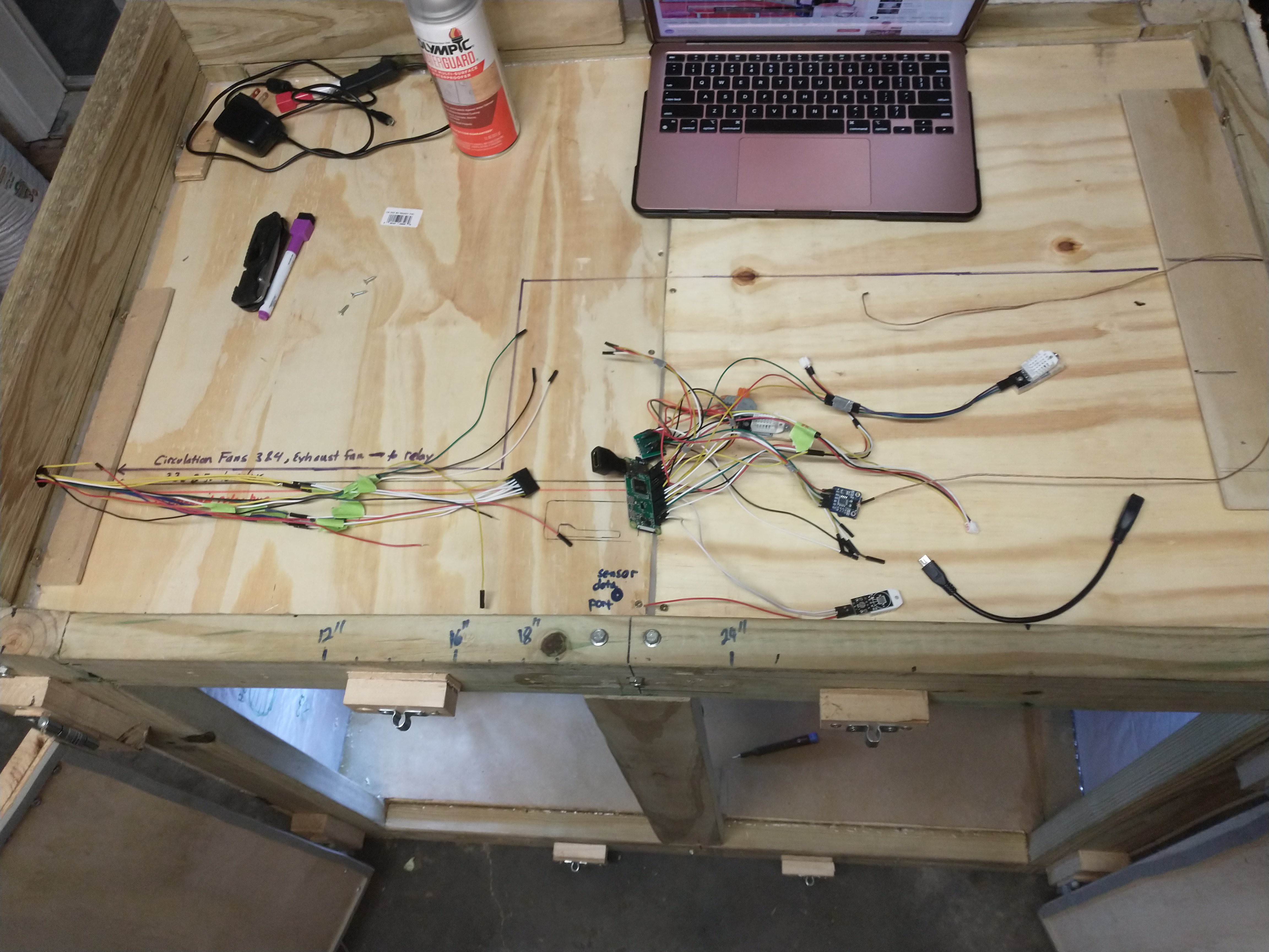
I created a prototype board to organize the bird nest of sensor and relay wires connecting to the Raspberry Pi GPIO. Instead of plugging into the default GPIO each sensor and relay gets a designated plug.
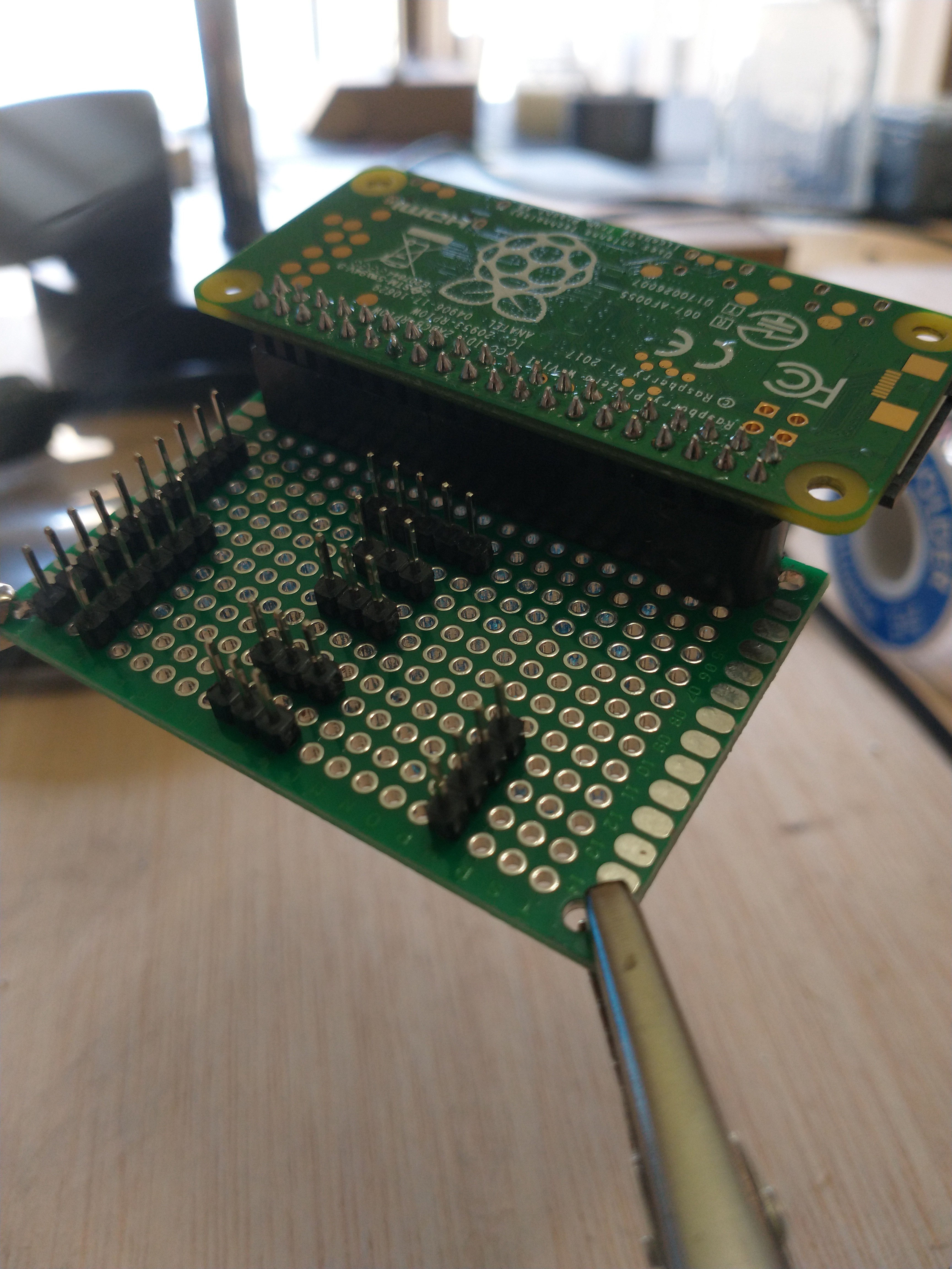
^ finished version 2 ( I had to scrap the first attempt and change the design). The left most pins are for the 8 channel relay (relay 2), and the row second from the left is for the 4 channel relay (relay 1). The top middle pins are for the MAX31855 thermocouple, and the 4 others in the middle are for DHT22 sensors. The first three DHT22s will be placed in the bottom, middle, and top section of the Mycobox, while the 4th is tracking the temperature and humidity outside of the box. The thermocouple is very precise and will have the most weight for controlling the PID that maintains the box temperature. Finally, the right most pins are for the co2 sensor, which is mounted just about midway in the MycoBox.
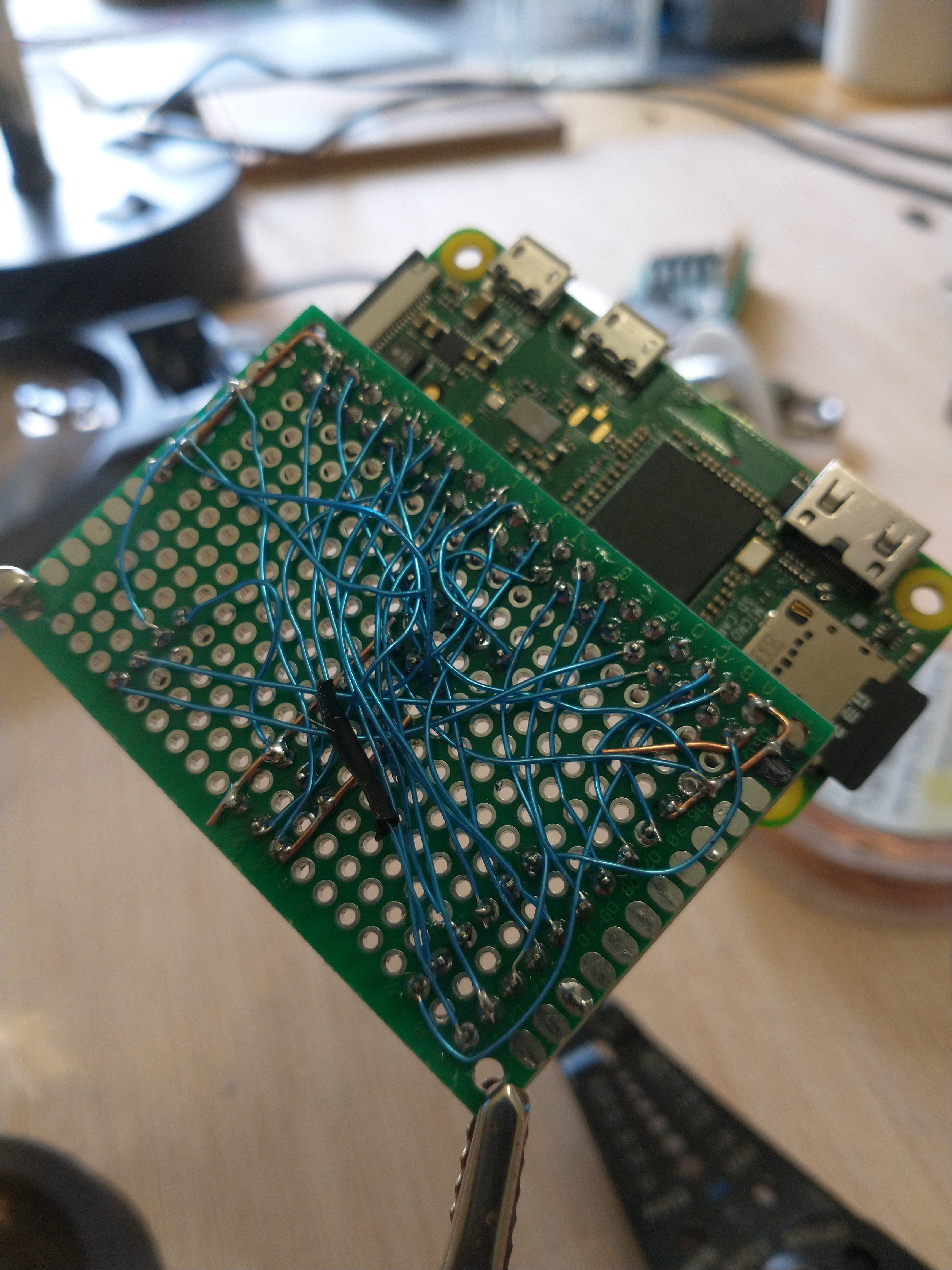
^ The bird nest is now tucked hidden under this board, never to be disturbed again
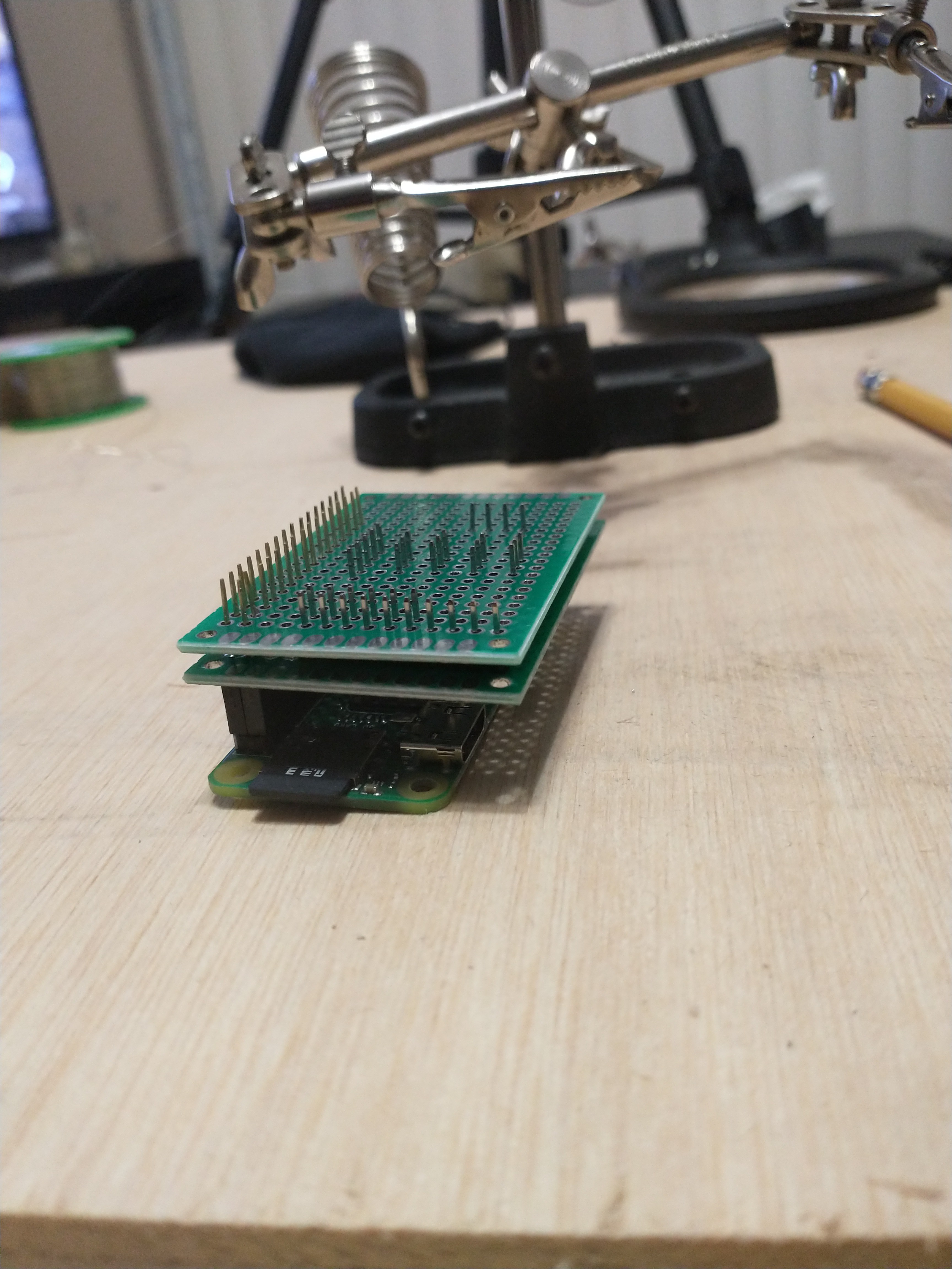
^ This is version 1, the original design that tragically didn't quite work. I placed the board directly above the Pi to reduce space and I soldered everything together in that middle layer, however the pins were not tall enough to attach to the sensors after added the second board like this.
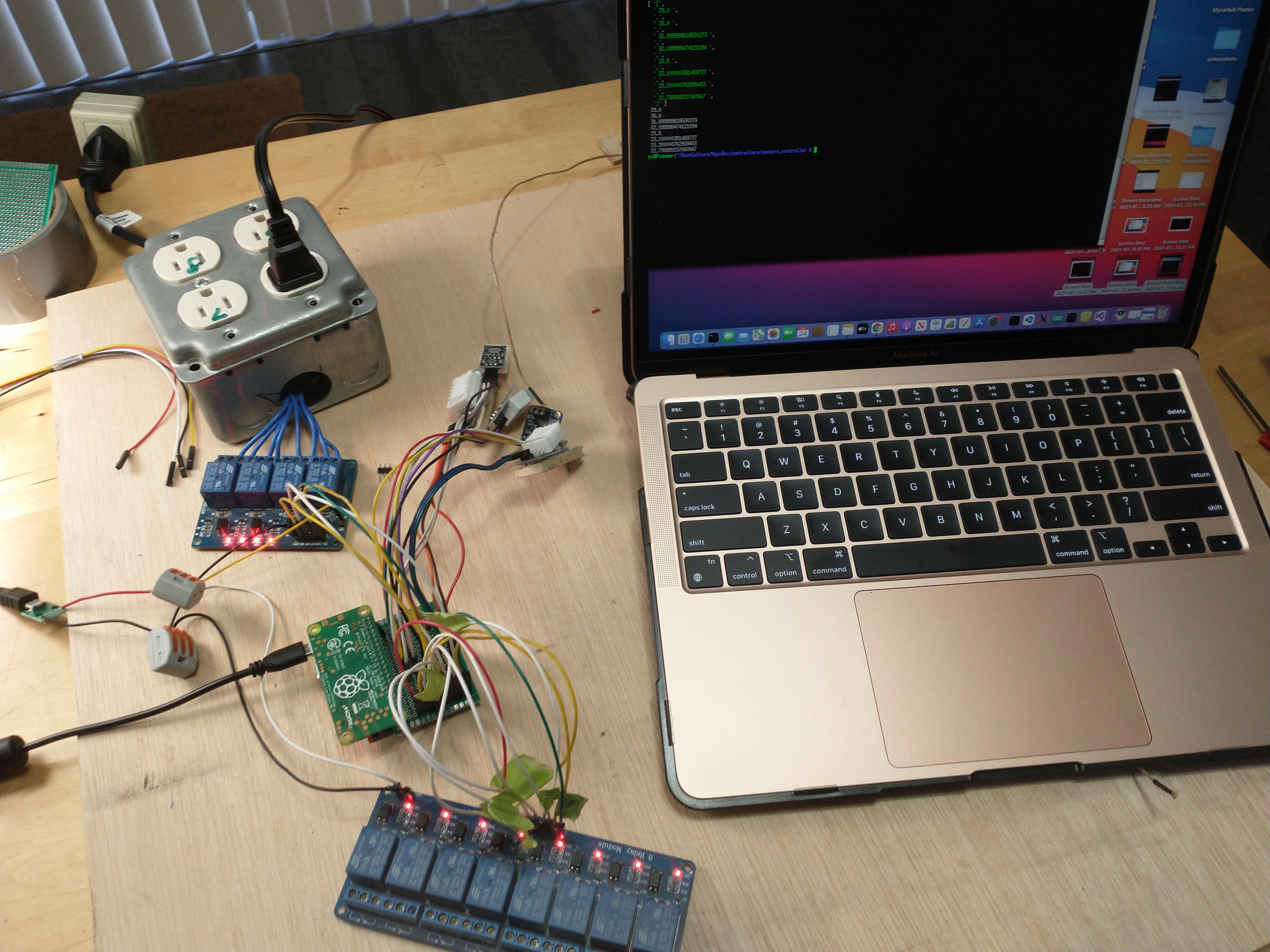
^ verifying that every relay and sensor is working; didn't verify the co2 meter yet, will do that tomorrow. I will also need to add a plug for the infrared temperature sensor. And I will be turning the sensor and relay wires into wrapped cables soon, which will look just a bit more organized.
4) Switched the AC port with a much smaller one
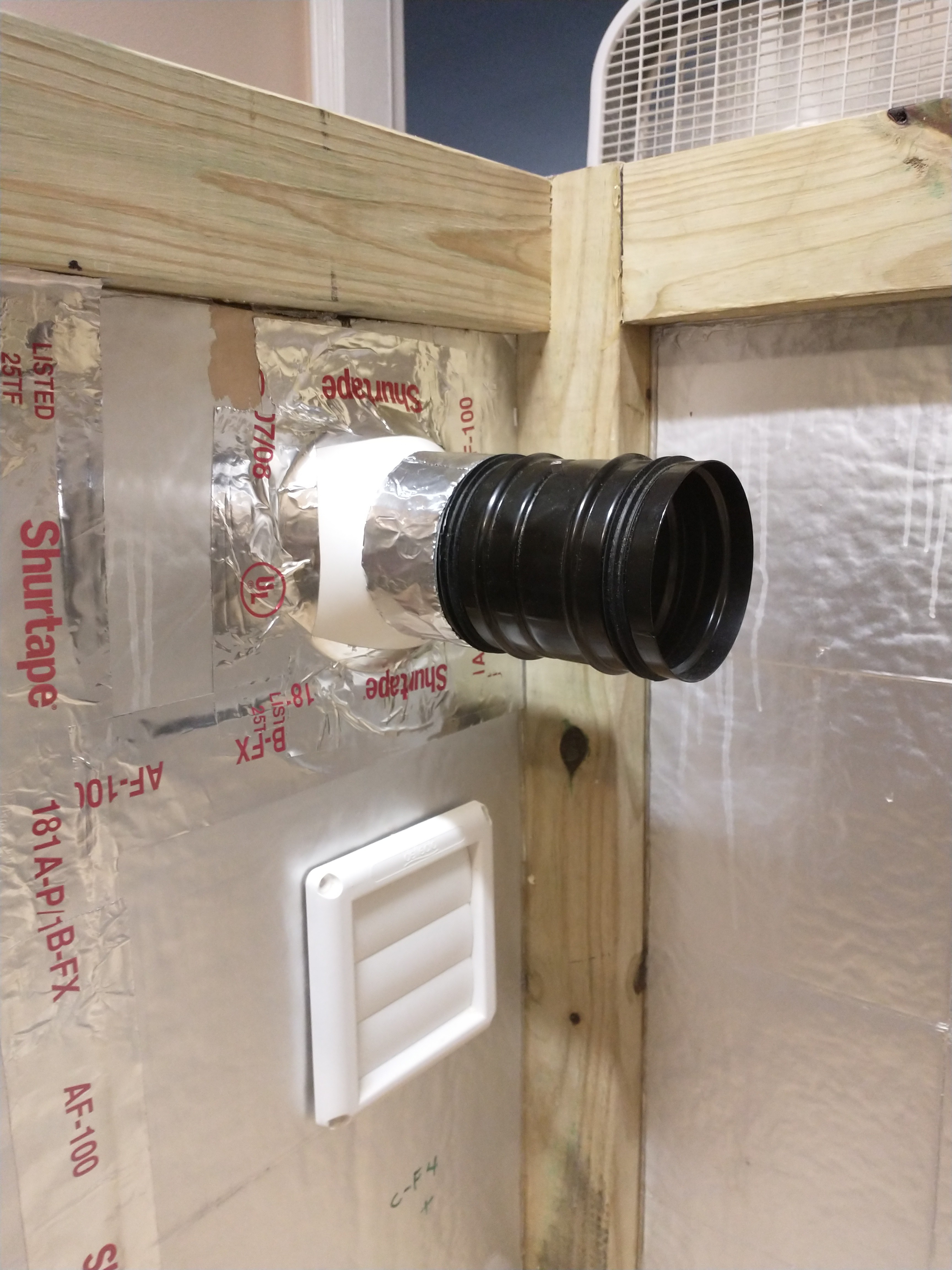
I switched the AC port with a much shorter one so that the butterfly vent doesn't stick quite as far into the grow chamber.
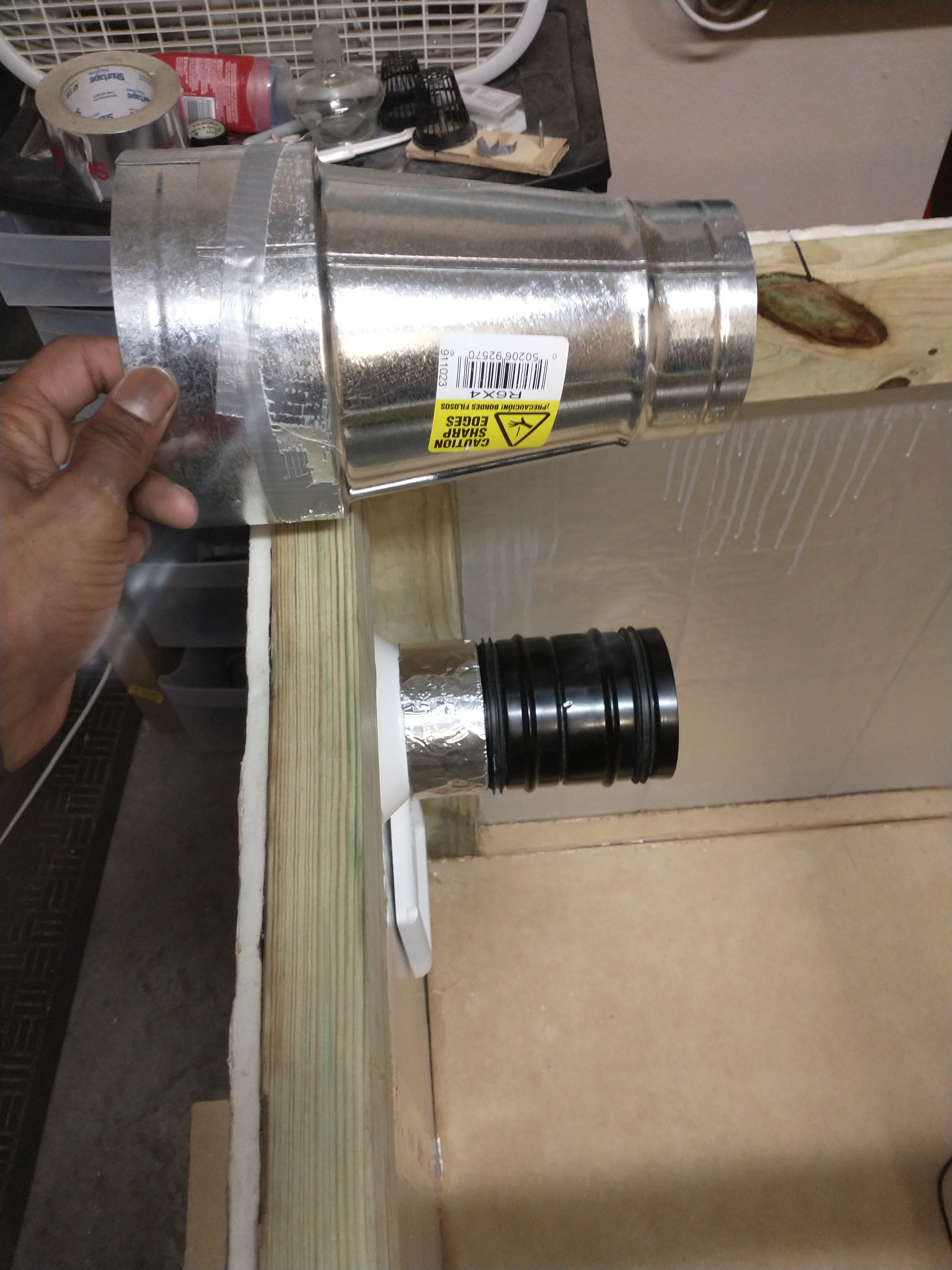
^ The previous port without the butterfly vent attached was as long as the new port with the vent. The previous port was the only one available at Home Depot and was really long for some reason.
Summary: I added the ceiling for the MycoBox and the pan for holding the raspberry pi, reduced the sized of the AC port, determined the design of the laminar flow hood, and nearly finished rewiring the MycoBox. My next post will have the finished wiring and maybe a software update demonstrating the environment manager actually setting the temperature in the chamber with the AC. The next hardware components I'll be adding are; the heater, humidifier, and the four circulation fans, and lights. After adding these remaining actuators and touching up the chamber with a bit more silicone, the MycoBox hardware will be almost completed (still need to add two webcams).
More that's coming soon:
I will be filling in the project details and posting photos and descriptions of the existing applications for sending commands to MycoBox; I said applications because there is an online web app (which I'm converting to an Electron cross platform true application I think), and I have a simple command line application that currently just manually overrides the relays. https://www.csimn.com/CSI_pages/PIDforDummies.html
Discussions
Become a Hackaday.io Member
Create an account to leave a comment. Already have an account? Log In.