 Mahesh Venkitachalam
I have uploaded glo 0.3 gerbers to OSHPark:
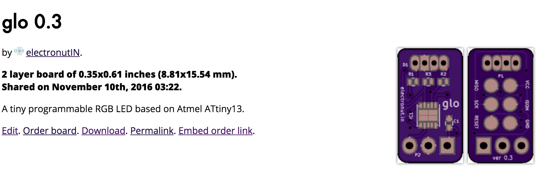
https://oshpark.com/shared_projects/Eu1TpIlK
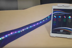
Here's a video of glo in action:
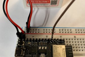
For the curious, the red PCB is snapVCC, a buck converter regulator I crowd-funded successfully last year:
A tiny programmable RGB LED based on Atmel ATtiny13.
Already have an account? Log in.
To make the experience fit your profile, pick a username and tell us what interests you.
I have uploaded glo 0.3 gerbers to OSHPark:
https://oshpark.com/shared_projects/Eu1TpIlK
Here's a video of glo in action:
For the curious, the red PCB is snapVCC, a buck converter regulator I crowd-funded successfully last year:
Thinking of implementing serial Rx on glo's GPIO pin so we can set the RGB values using a USB to serial adapter. The chip has 64 bytes of EEPROM so I could even store a pattern on it...


I also think this is pretty cool. I'm guessing the PCB is a voltage regulator to provide 5 volts to the circuit, is that correct Mahesh?
seems like more than that, and besides, you could just do that on the breadboard, or put the voltage regulator on the LED
What you say about using a breadboard mounted regulator is true of course. But if you look at the description and the schematic there are 3 connections to this module - VCC, GND and GPIO. There are only two wires coming from the PCB on the battery in the demo, so I assume that they must be VCC and GND (and they are red and black too) .
This is what leads me to suspect that the device on the battery is a voltage regulator. Perhaps the jumper on the board lets you select between 3.3 and 5 volts, if so it might be useful if you don't have a bench power supply.
But again I'm just guessing, Mahesh can fill us in on the details.

Hi Bill,
The PCB is indeed a voltage regulator which uses a buck converter. It's actually a product of mine called snapVCC which was crowd-funded last year:
https://hackaday.io/project/6269-snapvcc
Regards
Hi Mahesh
Thanks for clarifying. That's a pretty neat voltage regulator!
 kieron.gillespie
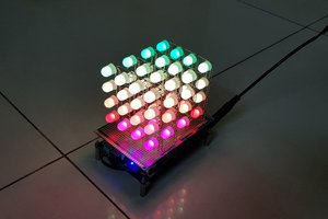
 tuenhi.n2012
cool project, but what is the PCB on the 9 volt for?