 davedarko
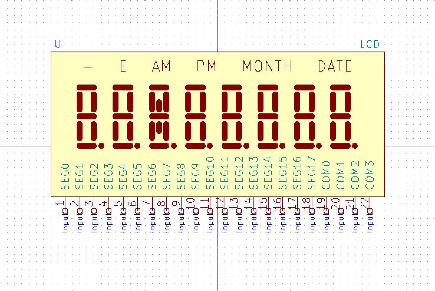
The blob chip on the PCB is on the other side of the contacts for the LCD of the PCB, so there are 22 vias that I was able to sand and solder to. I've cut the connection of the chip, so I basically ended up with a breakout board for the LCD. Because of it's "capacitive" nature the display showed something just by connecting the positive pin of the power supply to a segment pin (voltage not important as there was no circuit completed). At least I think that's the reason. I guess everyone has taken apart an LCD calculator and was fascinated that it shows something just by you touching the pads or pins of the display. Anyways, thanks to this "trick" I was able to see that the 22 pins of the LCD are 18 pins for groups of four segments and then 4 of course for one of that activated segment. Thee pinout is super straight forward, as the 4 common pins are the last 4 on the right.
Here's a screenshot of the KiCad symbol I'm working on right now
Discussions
Become a Hackaday.io Member
Create an account to leave a comment. Already have an account? Log In.