 Tim
TimCatching up on an additional round of synthesis test - from last year. I already implemented some changes after observing issues, so this is just an intermediate step.
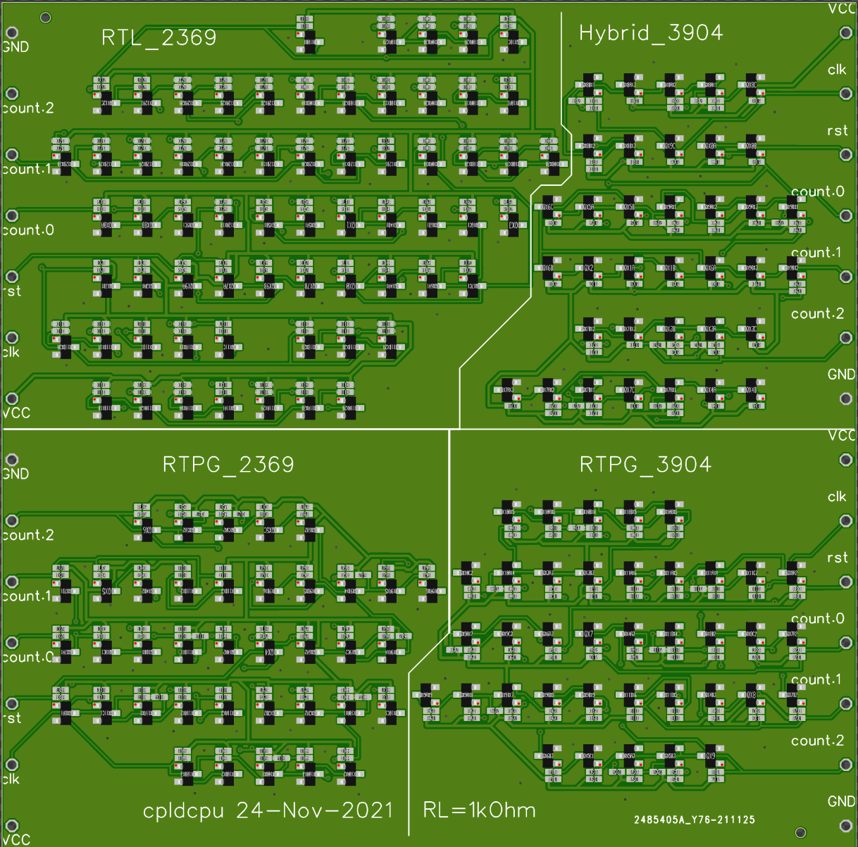
I combined counter implementation in four different logic families into one board of efficiency.
- RTL_2369: Resistor transistor logic with PMBT2369 and RL=RB=1kOhm
- RTPG_2369: RTL+Pass Gate Logic with PMBT2369 and RL=RB=1kOhm
- RTPG_3904: RTL+Pass Gate Logic with PMBT3904 and RL=RB=1kOhm
- Hybrid_3904: NMOS+Pass Gate Logic with 2N7002 and PMBT3904, RL=RB=1kOhm
PMBT2369 based Resistor Transistor Logic
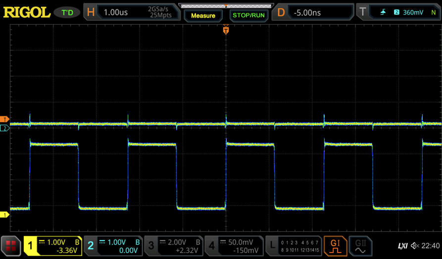
This implementation uses master-slave flipflop based on CDC6600 style polarity hold latches. This can be easily see from the spike that is introduced on a rising edge of the clock when the output is low.
I elected to go with a rather low load and base resistance to achieve maximum speed in this implementation. This results in a static current draw of 238mA. Furthermore, the signal generator in my scope with not able to drive the clock signal anymore due to too high load. I had to introduce as SN7407 as clock buffer.
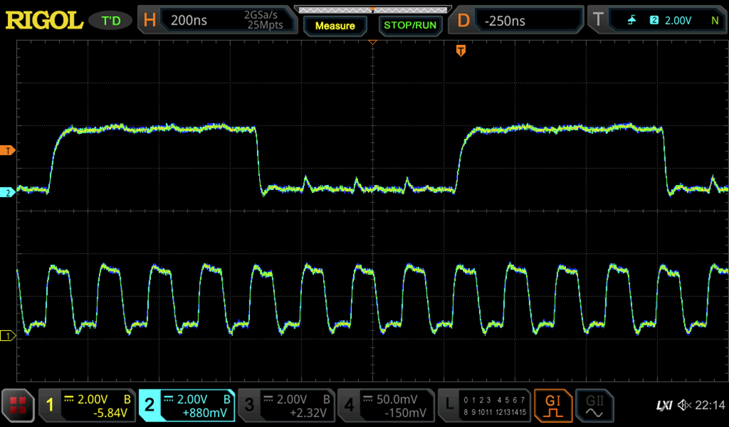
The scope image above showns the counter at 7 MHz, which is quite respectful.
Conclusions:
- PMBT2369 based RTL is fast
- 1 kOhm RL/RB is too low and would require introducing a proper clock signal distribution network.
- The PH-latch MS flipflop is somewhat unbalanced. Better DFF architecture needed.
PMBT2369 based RTPG (Resistor-Transistor-Pass-Gate) Logic
Next: RTL+Pass gate logic. This logic style uses pass gate transistors in 7T master-slave latch DFF. The purpose is to save transistors. In addition, there is a XOR2 basic gate using pass gate transistors.
We can see that this logic style does not work at all with the PMBT2369. This is actually consistent to simulation. The resaon is the low reverse beta on the PMBT2369 which does not allows it to function as a proper pass gate.
Conclusions:
- Cannot use pass gate logic with PMBT2369, so the pass gate logic style should be limited to slower transistors.
PMBT3904 based RTPG (Resistor-Transistor-Pass-Gate) Logic
RTL+Pass gate logic based on a normal PMBT3904 low cost switching transistor.
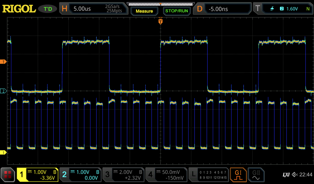
We can see above that the counter is working nicely. The current consumption is lower than RT at 182mA due to the much lower number of gates needed in this logic style. The maximum frequency is only 500kHz. This is owed to the slower transistors with high saturation charge and the inherently lower speed of this logic style (pass gate have no gain).
Conclusions:
- RTPG works well with low cost transistors and allows reducing number of transistors required for a certain logic implementation.
- The reduced are consumption is paid by very low switching speed.
- 1 kOhm load transistor is way too low and does not help increasing speed, since the circuit style is limited by saturation charge and pass transistors resistivity.
Hybrid NMOS-Pass-GateLogic
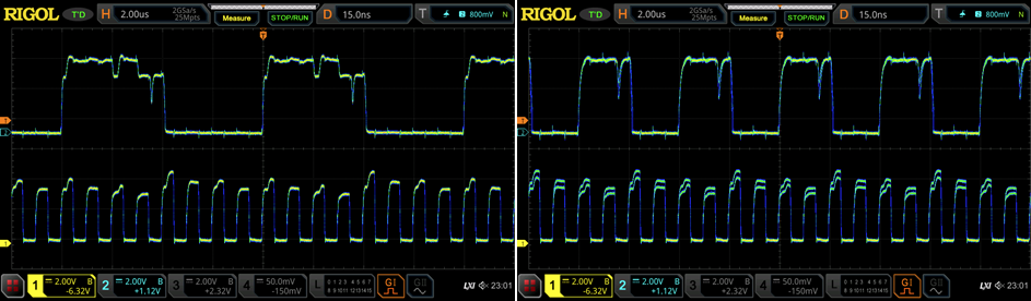
This logic style combined NMOS logic with NPN pass gates. The main purpose is to reduce the number of components as much as possible. The NMOS logic style does not require a base transistor and can implement a wider variety of gates than pure RTL. However, discrete NMOS power transistors, such as the 2N7002, cannot be used as pass gates due to the integrated reverse diode. Therefore NPN transistors are used.
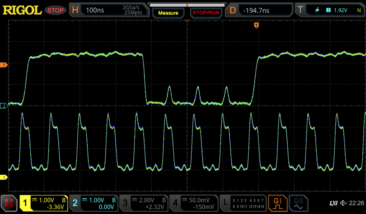
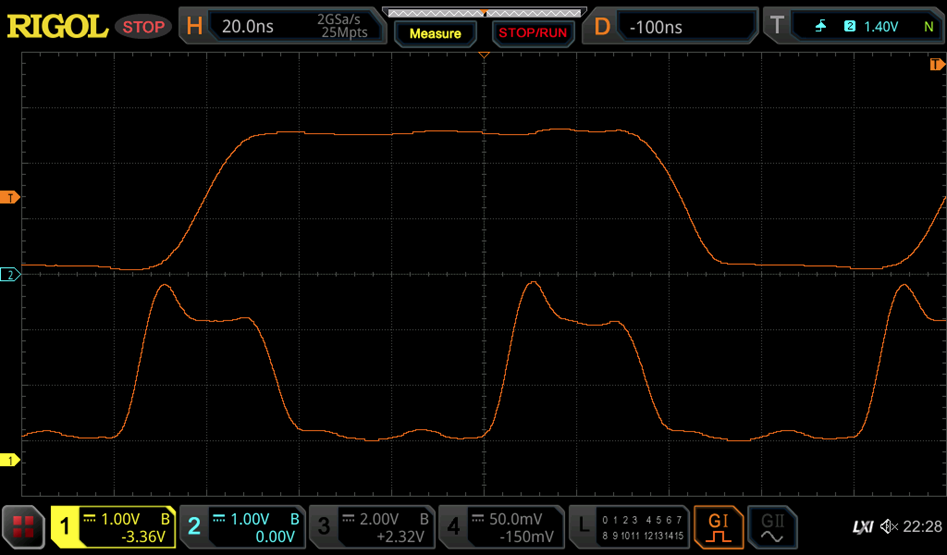
The scope images above show the counter in operation at 1 MHz. The waveforms look really nasty. The reason for this is the high gate charge of the 2N7002, which requires considerable time to switch to a new logic level. The speed is slightly better than RTPG at 1.7MHz. Current consumption is 140 mA.
Conclusions:
- Logic style works, but introduces a lot of switching noise. Waveforms are quite marginal.
- The number of saved transistors is not that high. Considering that 2N7002 are more expensive than MMBT3904, there is not much benefit apart from slightly higer speed.
- Probably not a good idea in general, so let's remove this one again.
Discussions
Become a Hackaday.io Member
Create an account to leave a comment. Already have an account? Log In.
Wow ! that is some awesome testing :-D
Are you sure? yes | no
That's a very old log. I think I need to continue working on this. I also added LTL in the mean time, but haven't worked on it for quite a while now.
Are you sure? yes | no
Well, I'm a bit late because I was busy with other things, but the "bipolar pass gate" trick is of great interest to me as you know :-)
Are you sure? yes | no