 Xasin
XasinLet's cut right to the chase - the item that most of you will most likely want to see:

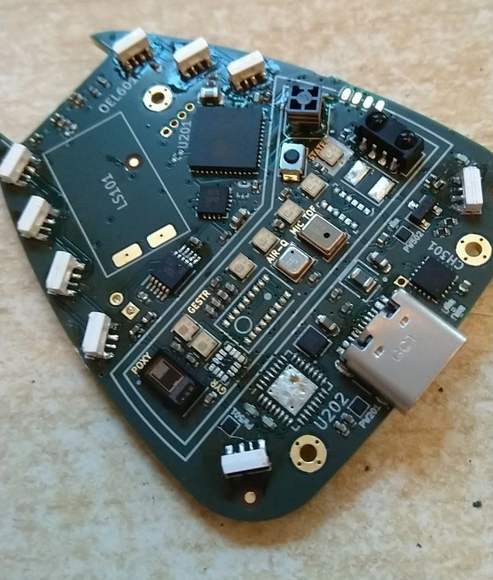
TapV2 has been soldered and has booted right up!
It was not, sadly, quite as first-try as we had been hoping, and a bunch of issues came up that will need to be fixed, but it's nothing major.
Look below the break to read up on how things went, what went wrong, how it almost blew up on us(!), and how we'll deal with that in the future!
Soldering
Soldering took place across a few hours, and went rather smoothly, all things considered!

All the soldering was completely on a single day, and actually went fairly smoothly!
Despite the fiducials, no automated P&P was used - all the components were laid down by hand, which made for a slightly stressful, mostly soothing day of carefully laying things down.
Sadly, a few parts either weren't there to begin with due to supply shortage, melted during the soldering, or had to be removed again.
These are:
- The STM32 and APDS-9500 are both missing due to component shortage, and there's no good way to ever really reach them, so for now they will remain out of reach.
- An old project was cut open to extract a MAX audio amplifier and LSM6DS3 MEMS IMU. Sadly, the IMU didn't make the transfer and had ended up shorting the power line, heating up in the process - it was desoldered again after testing, and a replacement sacrificial breakout board is on its way.
- The STM ToF sensor just... Melted. Not really sure who thought that regular plastic was a good choice for it, but it didn't withstand the hot air gun for long enough and was unusable, so it was removed before it was even fully soldered.
After soldering things up, a first test was performed, and... It was successful!
Most voltage lines were at the correct level, and the board drew only 20mA, which is what the ESP32's core would soak up without light sleep, so all seemed well!

The LEDs at first refused to work, as usual, but it turns out we had a bug in our NeoPixel code that... Somehow hadn't caused enough troubles for the past three years to be noticable? But it was quite easy to fix, and after adding a pragma pack(1) statement where it belonged, all seemed well enough.
The aftermath
Sadly, even though the LEDs were fixed easily, more problems were on the rise.
As we went to try and fit the PCB into the casing, it snagged and didn't want to close. It turns out the side-mount LEDs were a little too wide, and the clearance of the top half of the casing rubbed against them.
The bottom half also didn't leave enough clearance for the JST PH connector to wire up the battery, so both halves of the casings need to be reprinted. However, the way the diffusor looks is... Stunning to say the least, and breathtaking, to be honest. It looks better than I could have hoped for :)
There was one last, big issue that we still had to tackle:
While re-reading up on the battery charger IC's datasheet, which we mainly did just to be sure, we discovered, to our horror, that we had ordered a 4.35V battery charger by accident!!
The BQ24232 was the one we had wanted, but was out of stock. DigiKey had listed an alternative, the BQ24232H, which was also described as 4.2V Li-Ion charger...
That, however, was false. The H stands for high-voltage, and it very distinctly will overcharge the LiPo ever so slightly.
If we had not looked at the datasheet beforehand, this would have lead to a very unpleasant surprise after charging the battery for the first time!!
This, however, is not something we can easily deal with. The regular 4.2V charger is far from easily available, and will only be in stock by the end of 2022 - almost 2023!
For now we can still discharge the battery using it or power the system from USB only, but can only cautiously charge it up, leaving Tap without a safe battery system.
What's next?
So, what to do about all of this?
Well, luckily we can still start work on the most important items of the badge. The ESP32 works, the board can be powered without a battery, and once the replacement gyro and OLED screen are soldered in we can start working on the UI and a few first features.
However, with the star of the show, the Gesture Sensor, completely missing, and the battery system crippled due to the missing STM (which would have handled power-sequencing to reduce idle current) and wrongly numbered charge IC, it will take a while for the badge to show its full potential.
That certainly won't stop us though, and between the speaker, mic, LEDs, screen, BLE connection, BME680 and so on, there is enough to keep us busy for the next few weeks!
Discussions
Become a Hackaday.io Member
Create an account to leave a comment. Already have an account? Log In.