 kutluhan_aktar
First of all, to elicit assiduous gas measuring results, I chose to utilize these MQ series gas sensors by connecting them to the Arduino Nano:
- MQ-2
- MQ-3
- MQ-4
- MQ-6
- MQ-9
After choosing gas sensors for my device, I decided to control its settings and features with an IR remote control. Hence, I connected an IR remote receiver module to the Arduino Nano. Then, to display generated gas measurements, I used an ST7789 IPS screen.
Finally, I added a buzzer and a 5mm common anode RGB LED to get notified when gases reach dangerous levels.
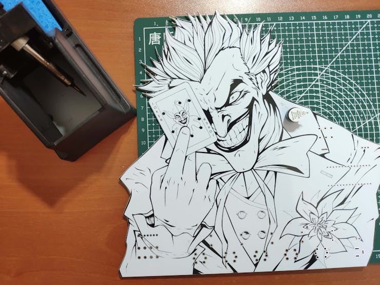
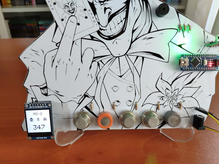
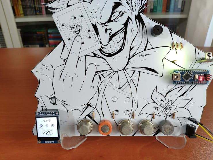
As you may have known, the toxic gas compound manufactured by Joker (Joker Venom or Laughing Gas) is considered remarkably dangerous in DC Universe. Hence, I shaped my device inspired by Joker's appearance in comics as a reminder of the detrimental effects of gases.
After completing wiring on a breadboard and testing the code, I designed my Joker-inspired PCB to complete my project. It became a stylish and intriguing addition to my workplace as an effective apparatus to monitor the presence of hazardous gases :)
Huge thanks to PCBWay for sponsoring this project.

Step 1: Designing and soldering the Joker Remote Gas Station PCB
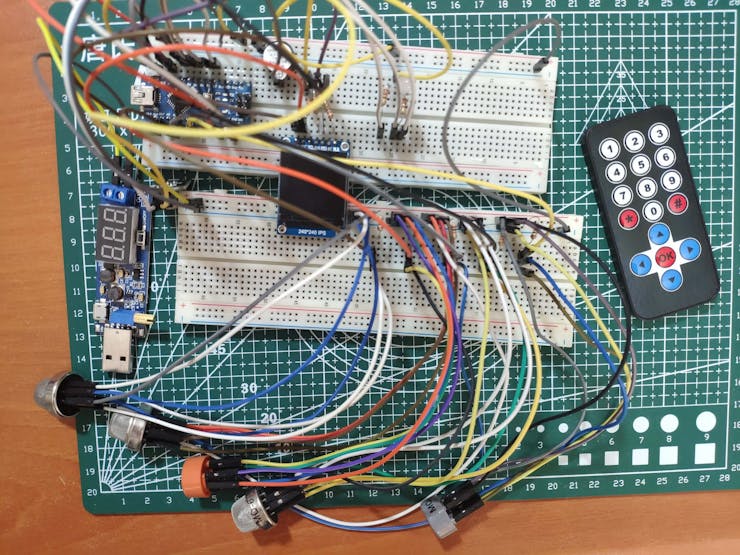
Before prototyping my PCB design, I tested all connections and wiring with the Arduino Nano on the breadboard.
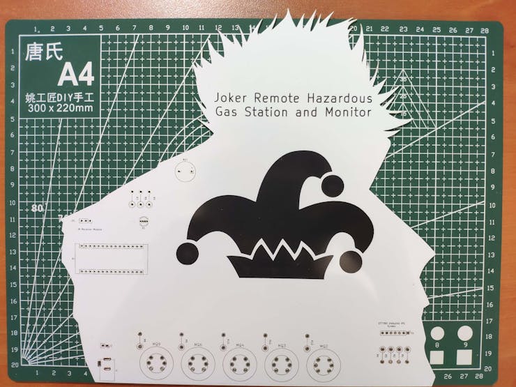
Then, I designed the Joker Remote Gas Station PCB by using KiCad. I attached the Gerber file of the PCB below, so if you want, you can order this PCB from PCBWay to create a fitting and apt apparatus to observe the presence of hazardous gases and get notified when they reach dangerous levels - inspired by malicious Joker :)
Click here to inspect and order this PCB directly on PCBWay.

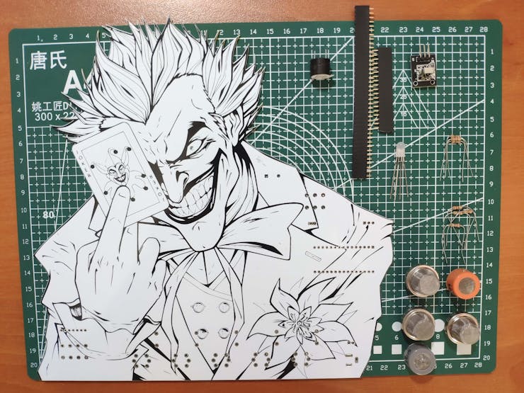
First of all, by utilizing a soldering iron, I attached Arduino Nano, IR receiver module, MQ-2 gas sensor, MQ-3 gas sensor, MQ-4 gas sensor, MQ-6 gas sensor, MQ-9 gas sensor, headers (female), buzzer, 5mm common anode RGB LED, 220Ω resistors, 20K resistors, and power jack.
Component list on the PCB:
A1 (Arduino Nano)
S1 (Headers for ST7789 IPS Screen)
IR1 (IR Receiver Module)
MQ2 (MQ-2 Gas Sensor)
MQ3 (MQ-3 Gas Sensor)
MQ4 (MQ-4 Gas Sensor)
MQ6 (MQ-6 Gas Sensor)
MQ9 (MQ-9 Gas Sensor)
BZ1 (Buzzer)
D1 (5mm Common Anode RGB LED)
R1, R2, R3, R4, R5, R6, R7 (220Ω Resistor)
R8, R9, R10, R11, R12 (20K Resistor)
J1 (Power Jack)
J2 (Headers for External Battery)

Step 2: Programming Arduino Nano and setting up components
Download the required library to be able to control the IR receiver module:
Arduino-IRremote | Library
Download the required libraries to be able to use the ST7789 240x240 IPS screen:
Arduino_ST7789_Fast | Library
Adafruit_GFX | Library
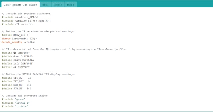
⭐ Include the required libraries.
⭐ Define the IR receiver module pin and settings.
#include <Adafruit_GFX.h>#include <Arduino_ST7789_Fast.h>#include <IRremote.h>// Define the IR receiver module pin and settings.#define RECV_PIN 2IRrecv irrecv(RECV_PIN); decode_results results;
⭐ By executing the IRrecvDemo.ino file in Examples, obtain the required IR codes from the IR remote control and define them.
#define up 0xFF18E7#define down 0xFF4AB5#define right 0xFF5AA5#define left 0xFF10EF#define ok 0xFF38C7
⭐ Define the ST7789 240x240 IPS display settings.
#define TFT_DC 10#define TFT_RST 9#define SCR_WD 240#define SCR_HT 240
⭐ To display images on the ST7789 screen, convert them to .c files by using this image converter below:
You can download the converted images I used in Downloads - gas.c, lethal.c, and toxic.c.
⭐ Include the converted images.
#include "gas.c"#include "lethal.c"#include "toxic.c"
⭐ Initiate the ST7789 240x240 IPS display.
Arduino_ST7789 tft = Arduino_ST7789(TFT_DC, TFT_RST);
⭐ Initiate the IR receiver module.
⭐ Start and clear the ST7789 240x240 IPS display.
irrecv.enableIRIn(); tft.init(SCR_WD, SCR_HT); tft.fillScreen(RGBto565(235, 46, 0));
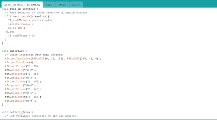
⭐ In the read_IR_controls function, collect IR codes from the IR remote control when transmitted.
void read_IR_controls(){ // Read received IR codes from the IR remote control. if(irrecv.decode(&results)){ IR_codeValue = results.value; irrecv.resume(); delay(500); }else{ IR_codeValue = 0; }}
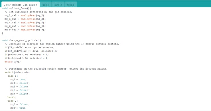
⭐ In the collect_Data function, get gas measurements produced by MQ series gas sensors - MQ-2, MQ-3, MQ-4, MQ-6, and MQ-9.
void collect_Data(){ // Get variables generated by the gas sensors. mq_2_val = analogRead(mq_2); mq_3_val = analogRead(mq_3); mq_4_val = analogRead(mq_4); mq_6_val = analogRead(mq_6); mq_9_val = analogRead(mq_9);}
⭐ In the interface function, print the interface with menu options.
void interface(){ // Print interface with menu options. tft.setTextColor(RGBto565(0, 38, 153), RGBto565(235, 46, 0)); tft.setTextSize(4); tft.setCursor(75, 25); tft.println("MQ-2"); tft.setCursor(75, 65); tft.println("MQ-3"); tft.setCursor(75, 105); tft.println("MQ-4"); tft.setCursor(75, 145); tft.println("MQ-6"); tft.setCursor(75, 185); tft.println("MQ-9");}
⭐ In the change_menu_options function, increase or decrease the option number by using the IR remote control buttons - Up and Down - to switch between menu options on the interface.
void change_menu_options(){ // Increase or decrease the option number using the IR remote control buttons. if(IR_codeValue == up) selected--; if(IR_codeValue == down) selected++; if(selected < 0) selected = 5; if(selected > 5) selected = 1; delay(100); // Depending on the selected option number, change the boolean status. switch(selected){ case 1: mq2 = true; mq3 = false; mq4 = false; mq6 = false; mq9 = false; break; case 2: mq2 = false; mq3 = true; mq4 = false; mq6 = false; mq9 = false; break; case 3: mq2 = false; mq3 = false; mq4 = true; mq6 = false; mq9 = false; break; case 4: mq2 = false; mq3 = false; mq4 = false; mq6 = true; mq9 = false; break; case 5: mq2 = false; mq3 = false; mq4 = false; mq6 = false; mq9 = true; break; }}

Step 2.1: Displaying the presence of hazardous gases
To detect the presence of hazardous gases, I utilized these five MQ series gas sensors:
- MQ-2
- MQ-3
- MQ-4
- MQ-6
- MQ-9
MQ-2 gas sensor has a high sensitivity to LPG, Propane, and Hydrogen, also can be used to detect Methane and other combustible steam.
MQ-3 gas sensor has a high sensitivity to Alcohol and has good resistance to gasoline, smoke, and vapor. This sensor can detect Alcohol with different concentrations.
MQ-4 gas sensor has a high sensitivity to Methane, Propane, and Butane. This sensor can detect different combustible gases.
MQ-6 gas sensor has a high sensitivity to Propane, Butane, and LPG, also response to Natural gas. This sensor can detect different combustible gases such as Natural gas, colorless flammable gaseous hydrocarbon consisting primarily of Methane and Ethane.
MQ-9 gas sensor has a high sensitivity to Carbon Monoxide, Methane, and LPG. This sensor can detect different gases containing CO and combustible gases.
As expected, after being connected to Arduino Nano, each sensor generates different value ranges depending on the amount of detectable hazardous gases.
After testing, I assigned these levels below for each sensor empirically. Change them after testing your sensors if required.
mq_2_val < 600 ➡ Low600 < mq_2_val < 700 ➡ Moderatemq_2_val >= 700 ➡ Dangerousmq_3_val < 650 ➡ Low650 < mq_3_val < 800 ➡ Moderatemq_3_val >= 800 ➡ Dangerousmq_4_val < 450 ➡ Low450 < mq_4_val < 600 ➡ Moderatemq_4_val >= 600 ➡ Dangerousmq_6_val < 500 ➡ Low500 < mq_6_val < 650 ➡ Moderatemq_6_val >= 650 ➡ Dangerousmq_9_val < 700 ➡ Low700 < mq_9_val < 850 ➡ Moderatemq_9_val >= 850 ➡ Dangerous
⭐ If a menu option is selected using the Up and Down buttons, highlight its name on the interface.

⭐ After being selected, if a menu option is activated using the OK button:
⭐ Collect and display the gas measurement value of the selected MQ series sensor with the converted images.
⭐ If the gas measurement value is Low according to the assigned levels, adjust the RGB LED to green.
⭐ If the gas measurement value is Moderate according to the assigned levels, adjust the RGB LED to yellow.
⭐ If the gas measurement value is Dangerous according to the assigned levels, adjust the RGB LED to red and turn on the buzzer to notify the user.
⭐ By pressing the Left button, return to the interface.
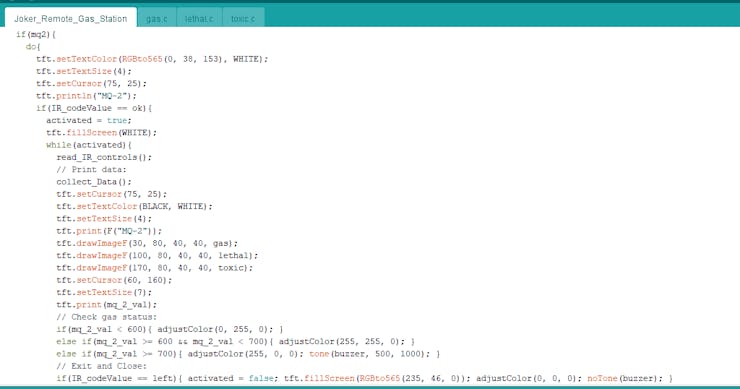
if(mq2){ do{ tft.setTextColor(RGBto565(0, 38, 153), WHITE); tft.setTextSize(4); tft.setCursor(75, 25); tft.println("MQ-2"); if(IR_codeValue == ok){ activated = true; tft.fillScreen(WHITE); while(activated){ read_IR_controls(); // Print data: collect_Data(); tft.setCursor(75, 25); tft.setTextColor(BLACK, WHITE); tft.setTextSize(4); tft.print(F("MQ-2")); tft.drawImageF(30, 80, 40, 40, gas); tft.drawImageF(100, 80, 40, 40, lethal); tft.drawImageF(170, 80, 40, 40, toxic); tft.setCursor(60, 160); tft.setTextSize(7); tft.print(mq_2_val); // Check gas status: if(mq_2_val < 600){ adjustColor(0, 255, 0); } else if(mq_2_val >= 600 && mq_2_val < 700){ adjustColor(255, 255, 0); } else if(mq_2_val >= 700){ adjustColor(255, 0, 0); tone(buzzer, 500, 1000); } // Exit and Close: if(IR_codeValue == left){ activated = false; tft.fillScreen(RGBto565(235, 46, 0)); adjustColor(0, 0, 0); noTone(buzzer); } } } }while(!mq2); } ...

Step 2.2: Fixing the timer0_pin_port error
Unfortunately, when using the IR remote library and the tone library, the Arduino IDE throws the timer0_pin_port error. The error occurs because both libraries try to use the timer by declaring the same name - Timer2.
To fix this issue, open the boarddefs.h or IRremoteBoardDefs.h file depending on the IR remote library version. Then, change IR_USE_TIMER2 to IR_USE_TIMER1 for Arduino Nano.

Connections and Adjustments
// Connections
// Arduino Nano :
//                                IR Receiver Module
// D2  --------------------------- S
//                                ST7789 240x240 IPS
// GND --------------------------- GND
// 3.3V -------------------------- VCC
// D13 --------------------------- SCL
// D11 --------------------------- SDA
// D9  --------------------------- RES
// D10 --------------------------- DC
//                                MQ-2 Air Quality Sensor
// A0  --------------------------- S
//                                MQ-3 Air Quality Sensor
// A1  --------------------------- S
//                                MQ-4 Air Quality Sensor
// A2  --------------------------- S
//                                MQ-6 Air Quality Sensor
// A3  --------------------------- S
//                                MQ-9 Air Quality Sensor
// A4  --------------------------- S
//                                5mm Common Anode RGB LED
// D3  --------------------------- R
// D5  --------------------------- G
// D6  --------------------------- B
//                                Buzzer
// D7  --------------------------- +
After completing soldering and uploading the code, I attached all remaining components to the board via headers - ST7789 240x240 IPS screen.

Unluckily, even though Arduino Nano works at 5V, the current provided by Nano is not enough for five MQ series gas sensors to get heated and generate accurate gas measurements. Thus, I added a power jack (J1) and a connector (J2) to my PCB design to supply the sensors with an external battery (5V).

Modes and Features
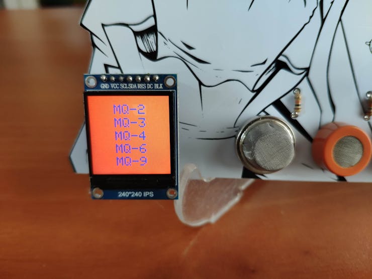
🤡🃏 The device shows five different MQ series sensors as menu options on the interface to display their gas measurements individually:
- MQ-2
- MQ-3
- MQ-4
- MQ-6
- MQ-9
🤡🃏 The device allows the user to switch between MQ series sensors (menu options) to observe their gas measurements via the IR remote control:
- Up Button ➡ Go Up
- Down Button ➡ Go Down
- OK Button ➡ Activate
🤡🃏 After activating any MQ series sensors by pressing the OK button of the IR remote control to display their gas measurements, the device lets the user return to the interface by pressing the Left button.
📌 MQ Series Sensors (Menu Options)
🤡🃏 If the MQ-2 option is selected and activated, the device shows its hazardous gas measurement value.
🤡🃏 Depending on the assigned measurement levels for the selected sensor (Step 2.1), the device adjusts the RGB LED:
- Green ➡ Low
- Yellow ➡ Moderate
- Red ➡ Dangerous
🤡🃏 The device turns on the buzzer if the hazardous gas measurement value is Dangerous according to the assigned levels.

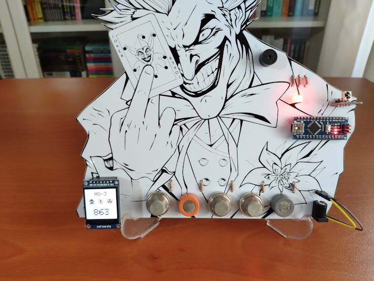
🤡🃏 If the MQ-3 option is selected and activated, the device shows its hazardous gas measurement value.
🤡🃏 Depending on the assigned measurement levels for the selected sensor (Step 2.1), the device adjusts the RGB LED:
- Green ➡ Low
- Yellow ➡ Moderate
- Red ➡ Dangerous
🤡🃏 The device turns on the buzzer if the hazardous gas measurement value is Dangerous according to the assigned levels.

🤡🃏 If the MQ-4 option is selected and activated, the device shows its hazardous gas measurement value.
🤡🃏 Depending on the assigned measurement levels for the selected sensor (Step 2.1), the device adjusts the RGB LED:
- Green ➡ Low
- Yellow ➡ Moderate
- Red ➡ Dangerous
🤡🃏 The device turns on the buzzer if the hazardous gas measurement value is Dangerous according to the assigned levels.


🤡🃏 If the MQ-6 option is selected and activated, the device shows its hazardous gas measurement value.
🤡🃏 Depending on the assigned measurement levels for the selected sensor (Step 2.1), the device adjusts the RGB LED:
- Green ➡ Low
- Yellow ➡ Moderate
- Red ➡ Dangerous
🤡🃏 The device turns on the buzzer if the hazardous gas measurement value is Dangerous according to the assigned levels.


🤡🃏 If the MQ-9 option is selected and activated, the device shows its hazardous gas measurement value.
🤡🃏 Depending on the assigned measurement levels for the selected sensor (Step 2.1), the device adjusts the RGB LED:
- Green ➡ Low
- Yellow ➡ Moderate
- Red ➡ Dangerous
🤡🃏 The device turns on the buzzer if the hazardous gas measurement value is Dangerous according to the assigned levels.

Videos and Conclusion
After completing all steps above, I placed the device on my desk by utilizing a plastic easel as an efficient assistant to detect the presence of hazardous gases in my workplace. It works impeccably :)
